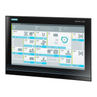
Home
Siemens
Industrial PC
SIMATIC IPC277E
Siemens SIMATIC IPC277E User Manual
5
of 1
of 1 rating
158 pages
Give review
Manual
Specs
To Next Page
To Next Page
To Previous Page
To Previous Page
Loading...
Overview
1.2
Conf
iguration of t
he devices
SIMATIC IPC277E
10
Operating Instructions, 11/2019, A
5E35783335-
AE
1.2
Configuration of the devices
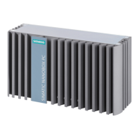
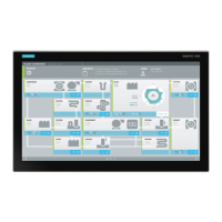
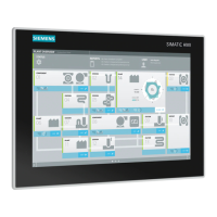
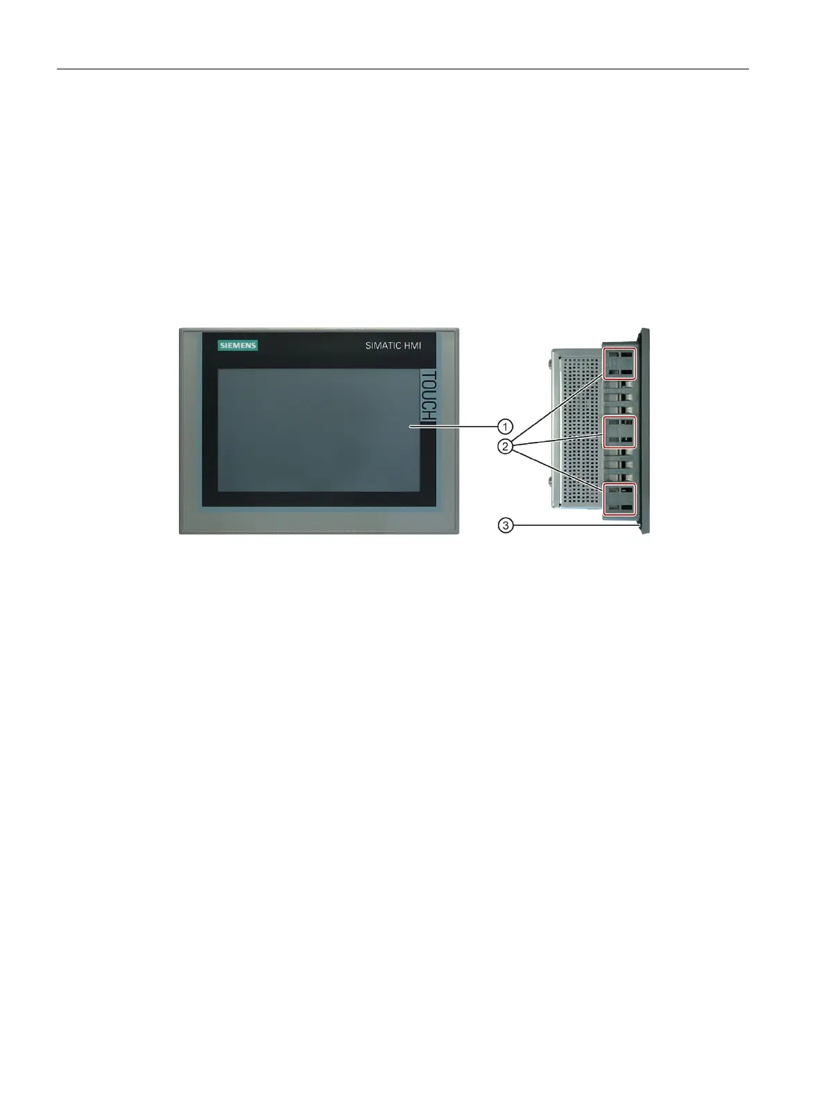
1.2.1
7" and 9" single
-
t
ouch devices
This section describe
s the design of the 7"
and 9" devices, using t
he 7" device as an
example.
Front and side view 7"
①
Display/touc
h screen
②
Recesses for
mounting
cli
ps
③
Mounting seal
9
11
Table of Contents
Default Chapter
3
Preface
3
Table of Contents
5
1 Overview
9
Product Description
9
Configuration of the Devices
10
7" and 9" Single-Touch Devices
10
12", 15" and 19" Single-Touch Devices
12
7" and 9" Devices - Interfaces und Operator Controls
15
12", 15", and 19" Single-Touch Devices - Interfaces and Operator Controls
16
12", 15", and 19" Multi-Touch Devices
17
12", 15", and 19" Multi-Touch Devices - Interfaces and Operator Controls
19
Accessories
20
2 Safety Instructions
23
General Safety Instructions
23
Notes on Usage
27
Use in Hazardous Areas
29
3 Installing and Connecting the Device
31
Preparing for Installation
31
Checking the Delivery Package
31
Identification Data of the Device
33
Permitted Mounting Positions
35
Preparing the Mounting Cutout
37
Installing the Device
39
Installation Guidelines
39
Secure with Mounting Clips
41
Mounting the Device with Mounting Brackets
43
Position of the Mounting Clips for Multi-Touch Devices
45
Fastening a Device Using a VESA Adapter
47
Connecting the Device
49
Notes on Connecting
49
Connecting the Protective Earth
51
Connecting the Power Supply to the 7" and 9" Devices
53
Connecting the Power Supply to the 12", 15 and 19" Devices
55
Connect Device to Networks
57
Mounting the Ethernet Connector Strain Relief
58
Securing Cables
58
Securing Cables for Use in Hazardous Areas
60
4 Commissioning the Device and Device Functions
61
Notes on Commissioning and Operation
61
Switching the Device On/Off
62
Advanced Device Functions
63
Monitoring Functions
63
Overview of the Monitoring Functions
63
Temperature Monitoring/Display
64
Watchdog (WD)
65
Battery Monitoring
66
Buffer Memory NVRAM
66
5 Operating the Device
67
Operator Input Options
67
IPC Driver and Tools
68
Operating a Device with Resistive Single-Touch Screen
69
Operating a Device with Capacitive Multi-Touch Screen
70
6 Device Expansion and Parameter Assignment
73
Open the Device
73
Installing and Removing Cfast Cards
75
7 Device Maintenance and Repairs
77
Maintenance
77
Repair Information
77
Cleaning the Device Front
79
Installing and Removing Hardware
80
Replacing the Backup Battery
80
Replacing the Drive
82
Installing the Software
83
Reinstalling the Operating System
83
Backing up Data
83
Recycling and Disposal
83
8 Technical Specifications
85
Certificates and Approvals
85
UL HAZ. LOC. and Atex/Iecex
86
Ex Approval
87
UL Approval
88
Australia, Class a
91
Directives and Declarations
92
Electromagnetic Compatibility for Industrial Environments
92
Rohs Directive
92
ESD Guideline
93
Dimension Drawings
96
Dimension Drawing of 7" Single-Touch Device
96
Dimension Drawing of 9" Single-Touch Device
97
Dimension Drawing of 12" Single-Touch Device
98
Dimension Drawing of 15" Single-Touch Device
99
Dimension Drawing of 19" Single-Touch Device
100
Dimension Drawing of 12" Multi-Touch Device
101
Dimension Drawing of 15" Multi-Touch Device
102
Dimension Drawing of 19" Multi-Touch Device
103
Technical Specifications
104
General Technical Specifications
104
Environmental Conditions
108
Shipbuilding
109
Power Supply 7" and 9" Device
109
Power Supply 12", 15" and 19" Device
111
Delivery State of the Pre-Installed Software
112
Boot Mode
112
Partitions in Windows Embedded Standard 7
112
Partitions under Windows 7 X64/X86 and Windows 10
113
Hardware Description
114
Technical Features of the Motherboard
114
External Interfaces
114
Overview of Interfaces
114
Serial Interface
115
Cfast
116
USB 2.0 Port
117
USB 3.0 Port
117
Ethernet Port
118
Displayport
119
System Resources
120
Currently Allocated System Resources
120
System Resources Used by the BIOS/DOS
120
Input/Output Address Areas
122
Overview of the Internal Module Registers
122
Watchdog Enable Register / 066H Select Register (Read/Write, Address 062H)
122
Watchdog Trigger Register (Read Only, Address 066H)
123
Battery Status Register (Read-Only, Address 50Ch)
123
NVRAM Address Register
124
BIOS Description
125
Overview
125
Opening the BIOS Selection Menu
126
Structure of the BIOS Setup Menu
128
Exit Menu
130
Default BIOS Setup Entries
131
BIOS Update
134
Alarm, Error and System Messages
135
Technical Support
137
Service and Support
137
Problem Solving
138
Markings and Symbols
139
Overview
139
Safety
139
Operator Controls
139
Safety-Relevant Symbols
140
Certificates, Approvals and Markings
141
Interfaces
142
List of Abbreviations
143
Glossary
147
Index
155
Other manuals for Siemens SIMATIC IPC277E
Operating Manual
54 pages
Quick Install Guide
2 pages
Compact Operating Instructions
10 pages
5
Based on 1 rating
Ask a question
Give review
Questions and Answers:
Need help?
Do you have a question about the Siemens SIMATIC IPC277E and is the answer not in the manual?
Ask a question
Siemens SIMATIC IPC277E Specifications
General
Brand
Siemens
Model
SIMATIC IPC277E
Category
Industrial PC
Language
English
Related product manuals
Siemens SIMATIC IPC277G
123 pages
Siemens simatic ipc227e
156 pages
Siemens SIMATIC IPC227G
115 pages
Siemens SIMATIC IPC
22 pages
Siemens SIMATIC IPC377E
124 pages
Siemens SIMATIC IPC477E
188 pages
Siemens SIMATIC IPC847E
212 pages
Siemens SIMATIC IPC627E
164 pages
Siemens SIMATIC IPC427E
164 pages
Siemens SIMATIC IPC547D
138 pages
Siemens SIMATIC IPC647E
200 pages
Siemens SIMATIC IPC627D
186 pages