System overview
3.5 Design
PN/BACnet LINK
Operating Instructions, 10/2017, A5E39895543-AA
17
Design
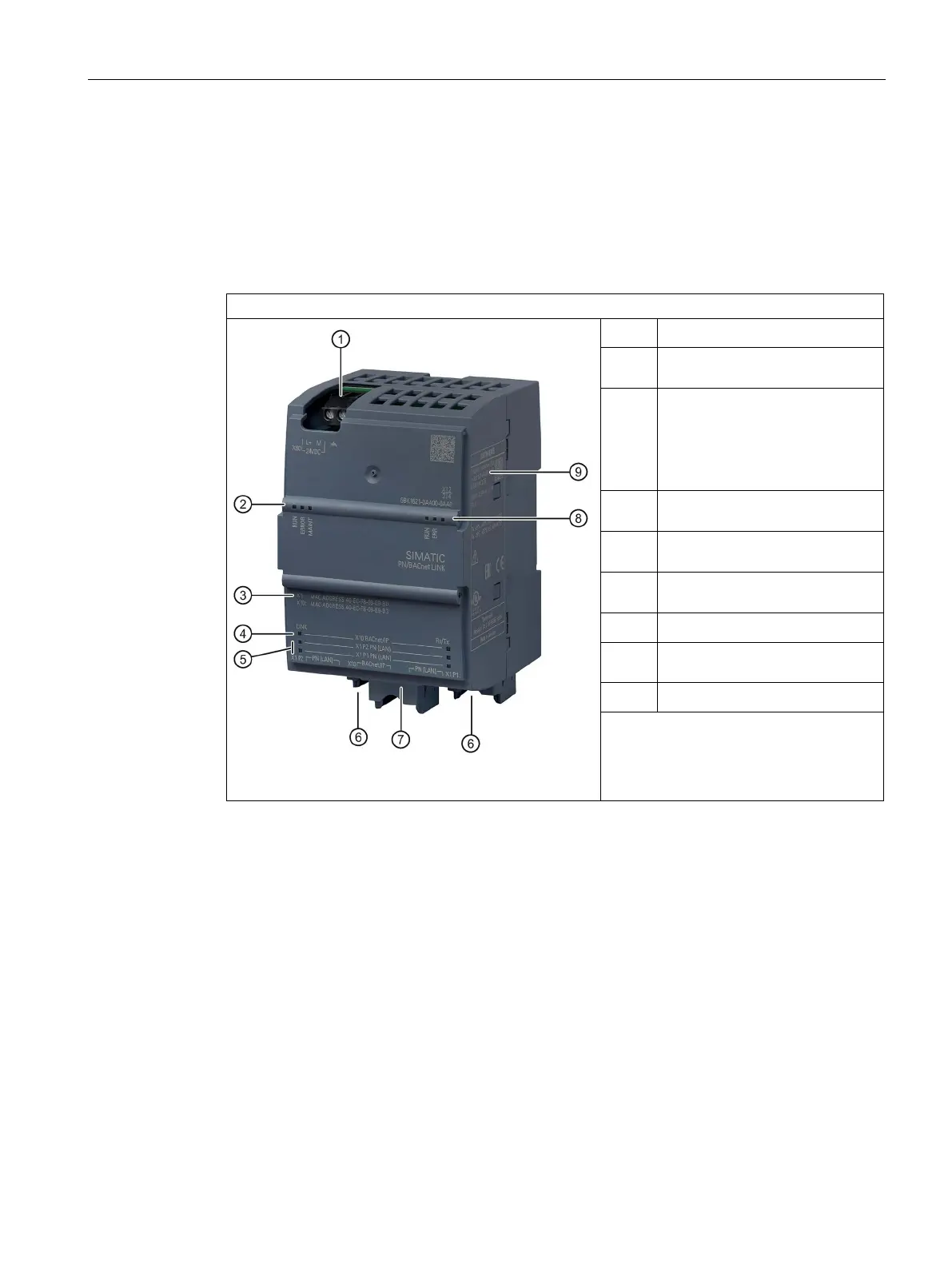
PN/BACnet LINK design
The figure below shows the arrangement of the connection and display elements on the
PN/BACnet LINK. The figure shows the device without a top and bottom enclosure cover.
PN/BACnet LINK design
24 V DC + functional grounding
②
Status LEDs device operating
MAC addresses
X1: Address that the device uses
on PROFINET
X10: Address that the device
④
Status LEDs Ethernet interface
Status LEDs Ethernet interface
for PROFINET
⑥
Ethernet connections for
Ethernet connection for BACnet
Status LEDs BACnet operating
state
Rating plate
24 V DC power supply (Page 55)
Connecting PROFINET (Page 57)
Connecting BACnet bus (Page 58)
Status LEDs (Page 77)
 Loading...