Commissioning
4.2 Connect the hardware
SIMATIC RF650R/RF680R/RF685R
26 Configuration Manual, 03/2018, C79000-G8976-C386-06
The reader is ready for operation when the "R/S" LED is lit/flashes green. If the "R/S" LED is
flashing, the reader is waiting for a connection. If the "R/S" LED is lit constantly, the reader is
connected to the controller or PC.
Pre-assembled cables therefore permit the ideal and simple connection of the reader. You
can find more information on the cables and wide-range power supply unit in the "SIMATIC
RF600" system manual.
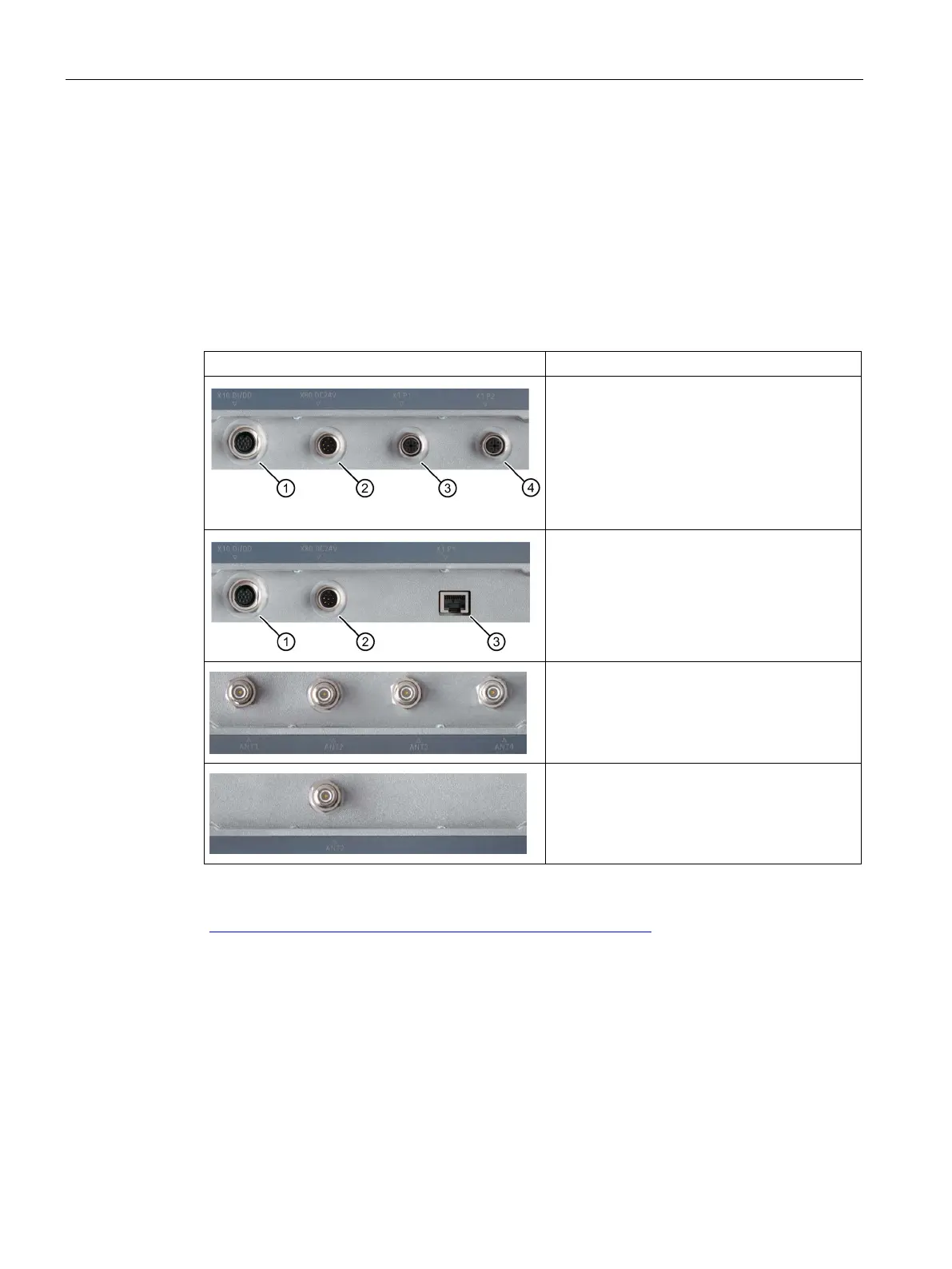
Table 4- 1 Interfaces and antenna connectors of the readers
Interfaces of the RF680R/RF685R readers
① Digital I/O interface (M12, 12-pin)
② Power supply 24 VDC and RS-422 (M12, 8-
pin)
③ Ethernet interface (M12, 4-pin)
Ethernet interface (M12, 4-pin)
Interfaces of the RF650R reader
① Digital I/O interface (M12, 12-pin)
② Power supply 24 VDC (M12, 8-pin)
③ Ethernet interface (RJ-45, 8-pin)
Antenna connectors of the RF650R/RF680R
readers
4 x antenna connectors for external antennas
(RP-TNC)
Antenna connector of the RF685R reader
1 x antenna connector for external antenna
(RP-TNC)
For detailed information on mounting the readers as well as ordering data of the readers and
cables, refer to the section "SIMATIC RF600 System Manual
(https://support.industry.siemens.com/cs/ww/en/view/22437600
)".