Appendix
A.1 Planning and installation of UHF read points
SIMATIC RF650R/RF680R/RF685R
Configuration Manual, 03/2018, C79000-G8976-C386-06
309
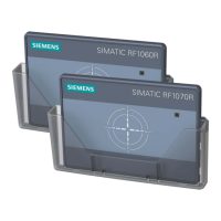
Identification situation with two transponders in an ideal radio/antenna field
Identification situation with two transponders in a real radio/antenna field with reflections that can
lead to obliteration and overshoots
Figure A-2 Propagation of UHF RFID antenna fields
Properties of the transmitting antenna
Depending on their design, UHF RFID antennas provide different properties. They differ in
the polarization and antenna gain.
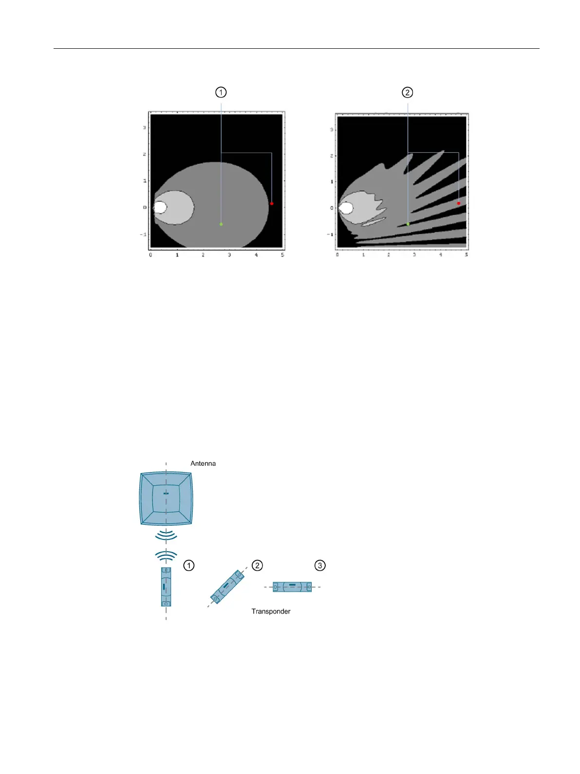
The direction of the electrical field component of an electromagnetic wave and the alignment
of the antenna decide the polarization of the radiation. A distinction is made between linear
and circular polarization of an antenna. With linear polarization you achieve the maximum
write/read distances when the polarization axes of the antenna and transponder are parallel
to each other. As the deviation increases, the received power deteriorates.
Polarization axes parallel: approx. 100 % range
Polarization axis turned through 45°: approx. 50% range
Polarization axis turned through 90°: approx. 10% range
Figure A-3 Effect of the polarization axes on the write/read distance with linear antennas