Getting Started
38 A5E37208904-003, 04/2017
−Absolute encoder cable connector,
−Brake cable connector. These connectors
should be ordered separately. For more information about the order information of the connectors, see the SINAMICS
V90, SIMOTICS S-1FL6 Operating Instructions.
•
The shaft height 90 mm motor has two M8 screw holes for eyebolts.
The former value indicates the dimension for high inertia motors with straight connectors; the latter value indicates the
dimension for high inertia motors with angular connectors.
Personal injury and material damage
Some motors, especially the 1FL609❑ are heavy. The excessive weight of the motor should be considered and any
necessary assistance required for mounting should be sought.
Otherwise, the motor can fall down during mounting. This can result in serious personal injury or material damage.
If the liquid enters the motor, the motor may be damaged
During motor installation or operation, make sure that no liquid (water, oil, etc.) can penetrate into the motor. Besides,
when installing the motor horizontally, make sure that the cable outlet faces downward to protect the motor from ingress of
oil or water.
Magnetic interference to the absolute encoder from the magnetic field
To avoid magnetic interference to the absolute encoder, keep the servo motor with an absolute encoder at least 15 mm
away from the devices that produce a magnetic field stronger than 10 mT.
Note
Using the eyebolts
The 1FL609❑ motor (90 mm shaft height) has two M8 screw holes for screwing in two eyebolts. Lift the
1FL609❑ motor only
at the eyebolts.
Eyebolts that have been screwed in must be either tightened or removed after mounting.
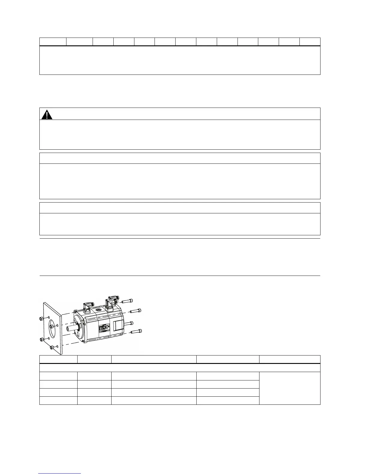
Install the motor onto a steel flange with four screws as shown in the following figure:

 Loading...


