Connecting
4.7 Motor holding brake
SINAMICS V90, SIMOTICS S-1FL6
Operating Instructions, 04/2019, A5E36037884-007
169
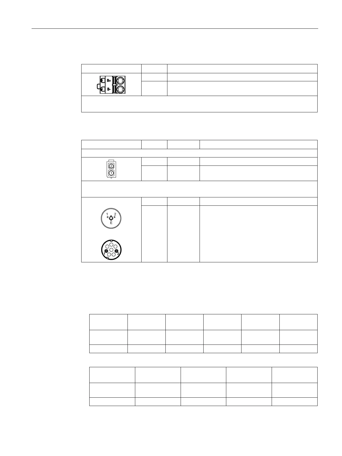
Motor holding brake interface - drive side (for 400 V variant servo drive only)
24 V, motor brake voltage positive
B- 0 V, motor brake voltage negative
Maximum conductor cross-section: 1.5 mm
2
Input voltage tolerance: 24 V ± 10%
Motor holding brake connector - motor side
Low inertia motor, shaft-height: 20 mm, 30 mm and 40 mm
2 Brake- Phase Brake-
Low inertia motor, shaft-height: 50 mm
High inertia motor, shaft-height: 45 mm, 65 mm, and 90 mm
Straight connectors:
Angular connectors:
2 Brake- Phase Brake-
The following table describes the states of various interfaces and components when the
brake works.
● 200 V variant
Brake en-
High level (1) Brake off Without cur-
Opened Cannot run
● 400 V variant
Brake engage-
High level (1) 0 V Opened Cannot run