Connecting
4.2 Main circuit wiring
SINAMICS V90, SIMOTICS S-1FL6
114 Operating Instructions, 04/2019, A5E36037884-007
Main circuit wiring
4.2.1
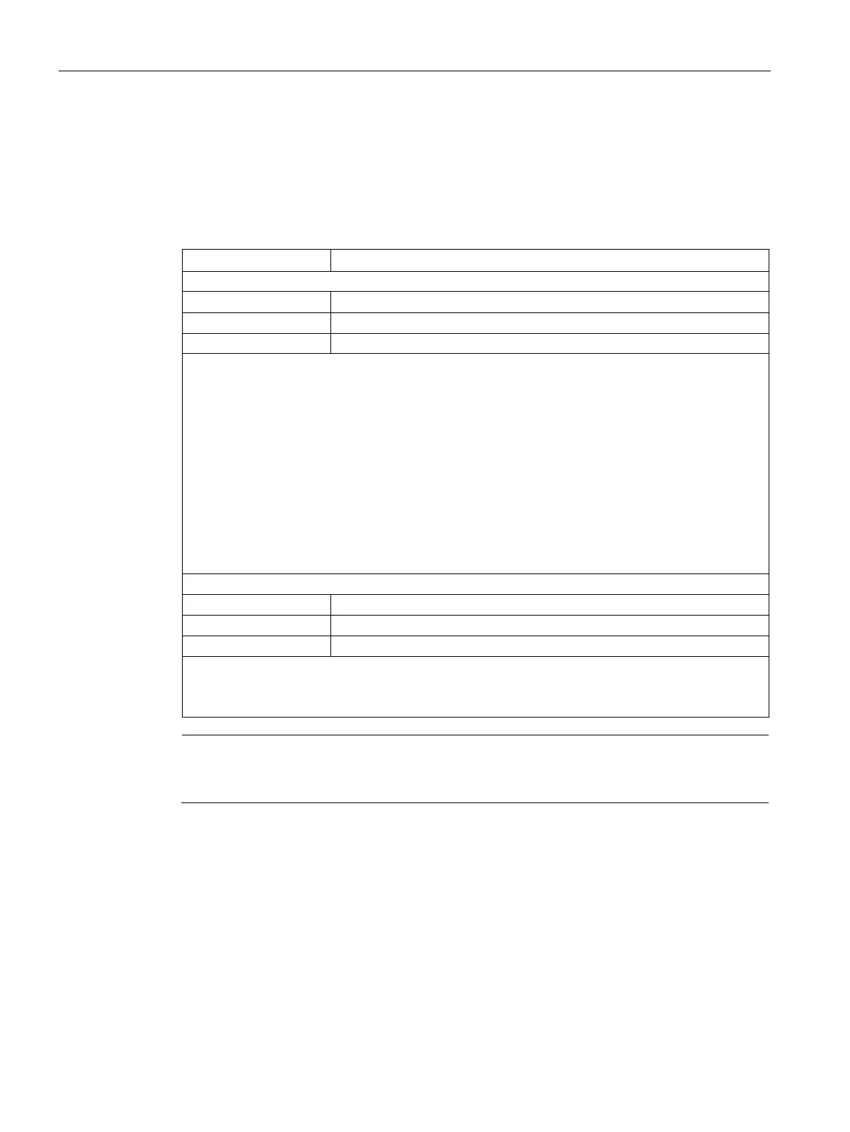
L1 Line phase L1
Recommended minimum cable cross-section:
When used on the single phase power network:
FSA: 0.75 mm
2
FSB: 0.52 mm
2
FSC: 1.31 mm
2
When used on the three phase power network:
FSA: 0.75 mm
2
FSB: 0.33 mm
2
FSC: 0.52 mm
2
FSD (1 kW): 0.82 mm
2
FSD (1.5 kW to 2 kW): 2.08 mm
2
Recommended minimum cable cross-section:
FSAA and FSA: 1.5 mm
2
2
Note
For 200 V variant servo drive, when using the FSA, FSB and FSC on the single phase power
network, you can connect the power supply to any two connectors of L1, L2, and L3.
Assembling the line supply cable terminals
The procedure of assembling a line supply cable terminal is the same as that for a power
cable terminal on the drive side.
For more information, see Section "Assembly of cable terminals/connectors on the drive side
(Page 411)".