EasyManuals Logo

Siemens SIMOTICS S-1FL6 User Manual

Siemens SIMOTICS S-1FL6
432 pages
To Next Page IconTo Next Page
To Previous Page IconTo Previous Page
Page #118 background imageLoading...
Page #118 background image
Connecting
4.2 Main circuit wiring
SINAMICS V90, SIMOTICS S-1FL6
116 Operating Instructions, 04/2019, A5E36037884-007
4.2.2
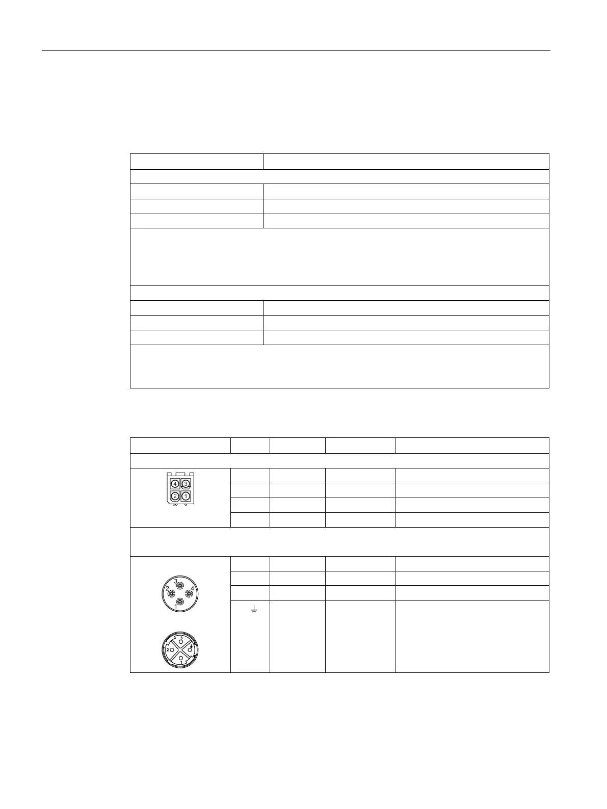
Motor power - U, V, W
Motor output - drive side
Signal
Description
200 V variant
U Motor phase U
V
Motor phase V
W Motor phase W
Recommended minimum cable cross-section:
FSA and FSB: 0.75 mm
2
FSC and FSD (1 kW): 0.75 mm
2
FSD (1.5 kW to 2 kW): 2.5 mm
2
400 V variant
U
Motor phase U
V
Motor phase V
W
Motor phase W
Recommended minimum cable cross-section:
FSAA and FSA: 1.5 mm
2
FSB and FSC: 2.5 mm
2
Power connector - motor side
Illustration
Pin No.
Signal
Color
Description
Low inertia motor, shaft-height: 20 mm, 30 mm, and 40 mm
1
U
Black
Phase U
2
V
Black
Phase V
3
W
Black
Phase W
4
PE
Yellow-green
Protective earthing
Low inertia motor, shaft-height: 50 mm
High inertia motor, shaft-height: 45 mm, 60 mm, and 90 mm
Straight connectors:
Angular connectors:
1 U Black Phase U
2
V
Black
Phase V
3 W Black Phase W
4/ PE Yellow-green Protective earthing

Table of Contents

Other manuals for Siemens SIMOTICS S-1FL6

Questions and Answers:

Question and Answer IconNeed help?

Do you have a question about the Siemens SIMOTICS S-1FL6 and is the answer not in the manual?

Siemens SIMOTICS S-1FL6 Specifications

General IconGeneral
BrandSiemens
ModelSIMOTICS S-1FL6
CategoryServo Drives
LanguageEnglish

Related product manuals