Control functions
7.6 Speed control (S)
SINAMICS V90, SIMOTICS S-1FL6
258 Operating Instructions, 04/2019, A5E36037884-007
Speed control with fixed speed setpoint
Parameter settings
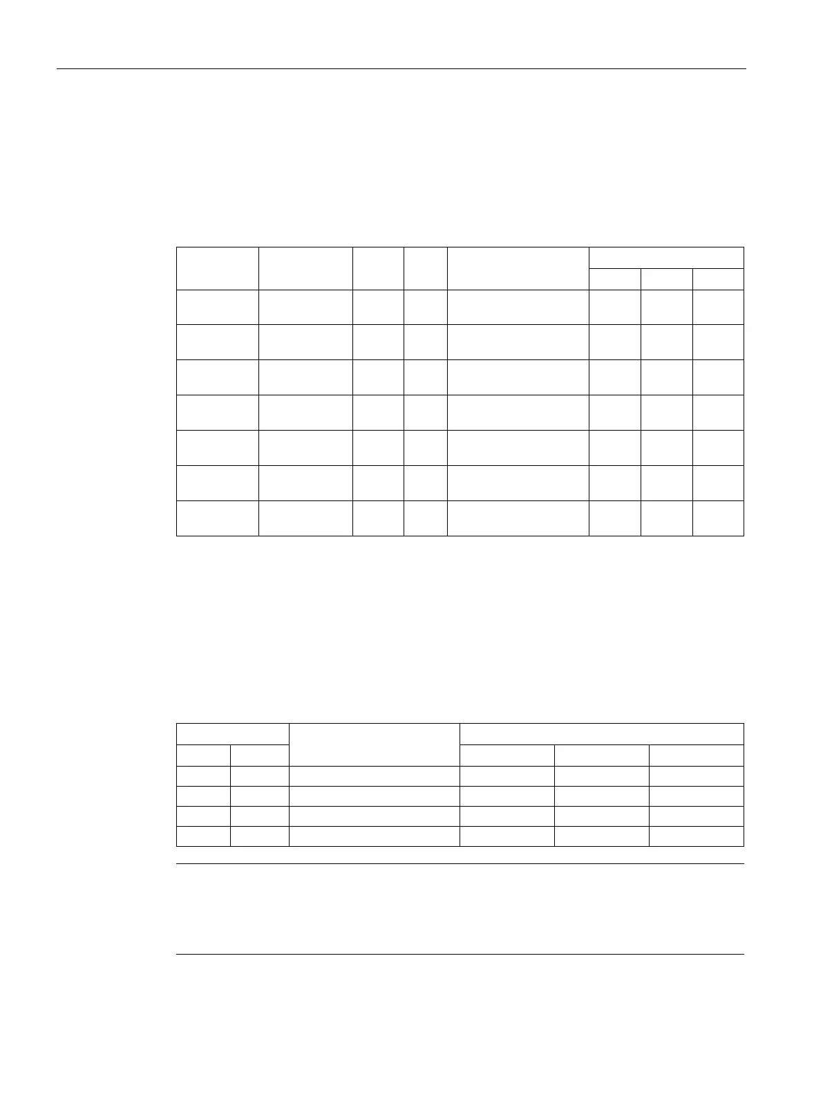
In the S mode, when at least one of the three digital input signals SPD1, SPD2 and SPD3 is
at high level, one of the following parameter values is used as speed setpoint.
p1001 -210000 to
0 rpm Fixed speed setpoint 1 0 0 1
p1002 -210000 to
0 rpm Fixed speed setpoint 2 0 1 0
p1003 -210000 to
0 rpm Fixed speed setpoint 3 0 1 1
p1004 -210000 to
0 rpm Fixed speed setpoint 4 1 0 0
p1005 -210000 to
0 rpm Fixed speed setpoint 5 1 0 1
p1006 -210000 to
0 rpm Fixed speed setpoint 6 1 1 0
p1007 -210000 to
0 rpm Fixed speed setpoint 7 1 1 1
Two digital input signals are used to control motor direction and run/stop.
● CWE: clockwise enable
● CCWE: counter-clockwise enable
The following table shows you in details:
Note
In S mode or T mode, when the servo motor is ready to run, signal CWE or CCWE is a must
to start running the motor.
For more information about signals
CWE and CCWE, refer to "DIs (Page 123)".