Connecting
4.3 Control/status interface - X8
SINAMICS V90, SIMOTICS S-1FL6
122 Operating Instructions, 04/2019, A5E36037884-007
Digital inputs/outputs (DIs/DOs)
SINAMICS V90 supports free assignment of signals to the following digital input and output
terminals depending on the control mode selected:
DI1 to DI8 -- Assignable with parameters p29301 to p29308
DO1 to DO6 -- Assignable with parameters p29330 to p29335
Exception: DI9 and DI10
DI9 is permanently assigned with the signal EMGS (quick stop) and DI10 is permanently
assigned with the signal C-MODE (change mode).
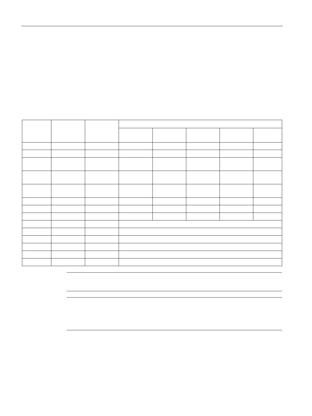
For detailed information about default DI/DO signal assignments, see the table below:
7 DI3 p29303 3 (CWL) 3 (CWL) 3 (CWL) 3 (CWL) 8
8 DI4 p29304 4 (CCWL) 4 (CCWL) 4 (CCWL) 4 (CCWL) 9
9 DI5 p29305 5 (G-
5 (G-
12 (CWE) 12 (CWE) 5 (G-
Note
The selected DI signal will respond with a delay time of 8 ms to 16 ms.
Note
DO signal inverse
The l
ogics of digital output signals DO1 to DO6 can be inversed. You can inverse the logics
of DO1 to DO6 by setting the bit 0 to bit 5 of parameter p0748.