Connecting
4.3 Control/status interface - X8
SINAMICS V90, SIMOTICS S-1FL6
Operating Instructions, 04/2019, A5E36037884-007
121
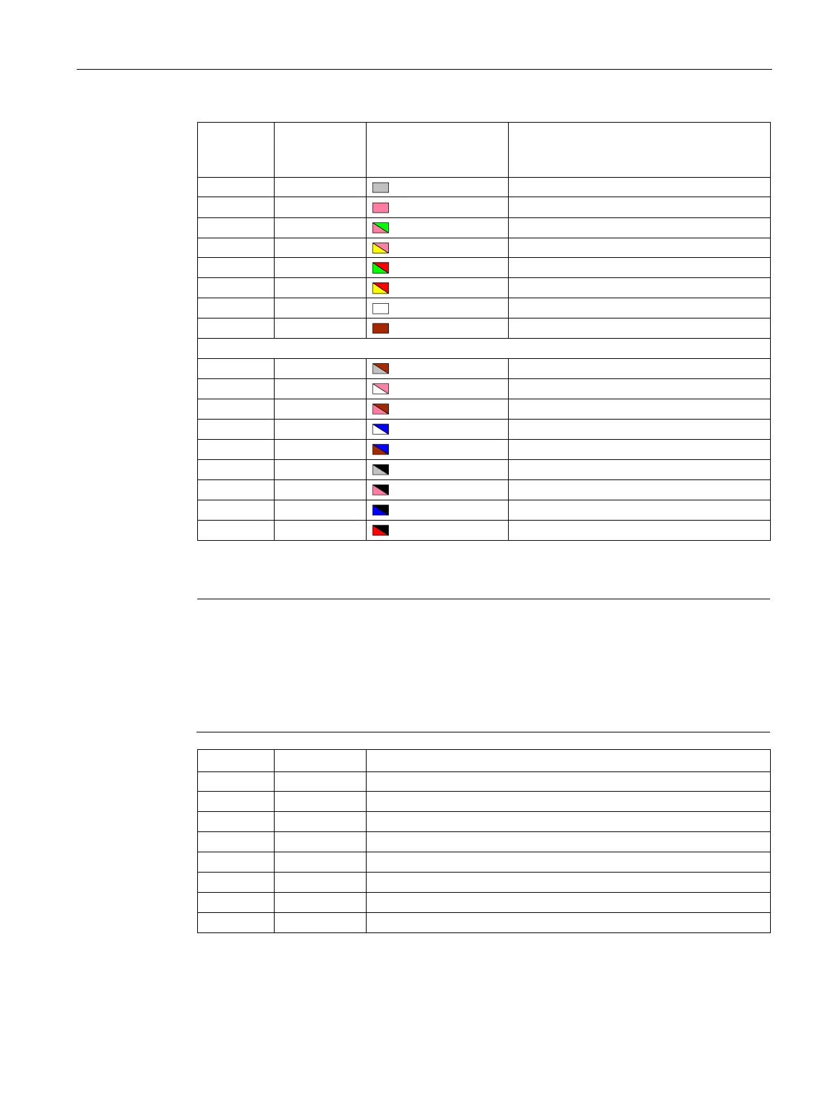
Wire color on the set-
point cable exposed
side
32 DO3 Pink Digital output 3
External 24 V ground for digital outputs
12 V power output for analog input
Analog input channel 1, positive
Analog input channel 1, negative
Analog input channel 2, positive
Analog input channel 2, negative
Refer to the following table for the original definitions of the above pins with an asterisk (*),
wherein DO4 to DO6 are used for the servo drive to support the wiring of
the NPN type.
Note
The original pin definitions are applicable only when the FS version is as follows:
V90 200 V: FS01
V90 400 V: FS03 and the earlier
r to the rating plate on the drive housing for the FS version of a SINAMICS V90 servo
External 24 V supply for digital outputs
External 24 V ground for digital outputs