Appendix
A.2 Motor selection
SINAMICS V90, SIMOTICS S-1FL6
424 Operating Instructions, 04/2019, A5E36037884-007
Inertia and inertia ratio
Inertia refers to the force required to keep a certain physical state. Inertia ratio indicates
dynamic response performance of motors. The smaller the inertia ratio is the better response
performance a motor has.
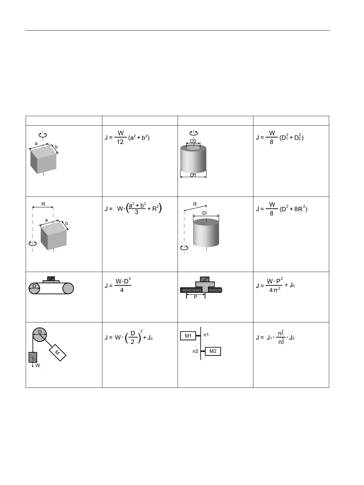
Typical load inertia equations
Axis of rotation on center
W: Mass (kg)
a: Length (m)
b: Width (m)
Axis of rotation on center
W: Mass (kg)
D
1
: External diameter (m)
D
2
: Internal diameter (m)
Axis of rotation off center
W: Mass (kg)
a: Length (m)
b: Width (m)
R: Rotational diameter (m)
Axis of rotation off center
W: Mass (kg)
D: Workpiece diameter (m)
R: Rotational diameter (m)
Conveyor
W: Mass (kg)
D: Pulley wheel diameter (m)
Ball screw
W: Mass (kg)
P: Lead (m)
b
: Ball screw inertia (kg·m
2
Object hung with pulley
W: Mass (kg)
D: Pulley wheel diameter (m)
J
p
: Pulley inertia (kg·m
2
)
Reducer
W: Mass (kg)
n
1
/n
2
: Speed of each motor
(rpm)
J
1
/J
2
: Inertia of each motor
2