Connections 02.2001 SLE / SLE-DP – SIMOLINK Encoder
GWE-477 763 4070.76 J Siemens AG
5-2 Operating Instructions SIMOVERT MASTERDRIVES
5.2 Encoder interface (X2 on SLE, X21 on SLE-DP)
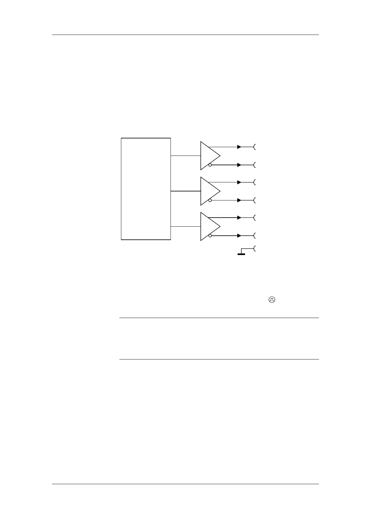
The encoder interface of the SIMOLINK Encoder is the 9-pin, SUB D
socket with screw locking mechanism (UNC) on the front of the
housing. Three RS422 drivers each supply two signals per pulse
output, one with non-inverted signal level and one with inverted signal
level. The output signals of the encoder interface are isolated from the
24 V supply voltage (X1) and (on the SLE-DP) from the PROFIBUS
interface (X22).
Frequency/signal
generator
A+
A
−
B+
B
−
GND
Zero +
Zero
−
Electrically isolated from
24 V supply voltage
1
6
3
8
2
7
9
Fig. 5-2 Schematic of output circuit
The encoder interface on the SLE module is labeled X2. The encoder
interface on the SLE-DP module has the designation X21, but is also
labeled with "PULSE OUT" and the following symbol:
The connector hardware for both the encoder interface and the
PROFIBUS interface is a 9-pin SUB D socket. The two interfaces are
distinguishable only by their labeling and position (cf. Fig. 4-3). The
plug and socket must be connected correctly by the end-user during
installation.
CAUTION