SLE / SLE-DP – SIMOLINK Encoder 02.2001 Connections
Siemens AG GWE-477 763 4070.76 J
SIMOVERT MASTERDRIVES Operating Instructions 5-5
5.3 PROFIBUS interface (X22 on SLE-DP)
The interface between the SLE-DP and the PROFIBUS line is the
EN 50170-compliant 9-pin SUB D socket with screw locking
mechanism (UNC) on the front of the housing. It is labeled with the
designation X22 as well as "PROFIBUS" and the following symbol:
.
The interface supplies an electrically isolated, short-circuit-proof supply
voltage for the optional connection of an OLP (Optical Link Plug). All
PROFIBUS signals are isolated from the 24 V voltage supply (X1) and
the encoder signals (X21).
The connector hardware for both the encoder interface and the
PROFIBUS interface is a 9-pin SUB D socket. The two interfaces can
be distinguished only by their labeling and position (cf. Fig. 4-3). The
plug and socket must be connected correctly by the end-user during
installation.
Pin Signal Meaning Range
1 Unused n.c.
2 Unused n.c.
3 RxD/TxD-P PROFIBUS data - P (non-inverted) RS485
4 CNTR-P Control signal for PROFIBUS OLP TTL
5 DGND Ground for PROFIBUS data 0 V
6 VP Positive supply voltage for
terminating resistor and OLP
DC + 5 V ± 10 %
for OLP
max. 100 mA
7 Unused n.c.
8 RxD/TxD-N PROFIBUS data - N (inverted) RS485
9 Unused n.c.
Housing Outer shield
9-pin SUB D socket with screw locking mechanism (UNC)
Table 5-4 Assignments of PROFIBUS interface connector (X22 on SLE-DP)
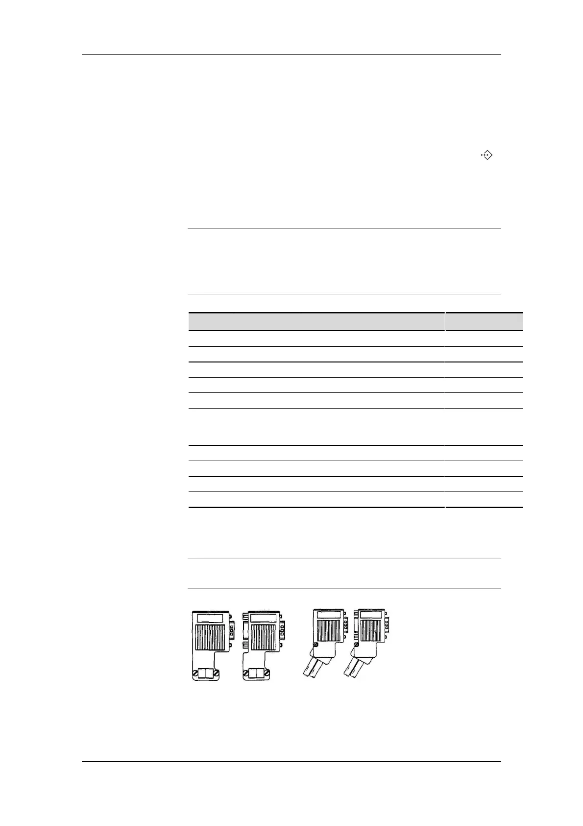
The cables must be connected by means of PROFIBUS connectors
since these contain the bus terminating resistors.
Fig. 5-3 Suitable PROFIBUS connectors
CAUTION
NOTE