Start-Up 02.2001 SLE / SLE-DP – SIMOLINK Encoder
GWE-477 763 4070.76 J Siemens AG
6-6 Operating Instructions SIMOVERT MASTERDRIVES
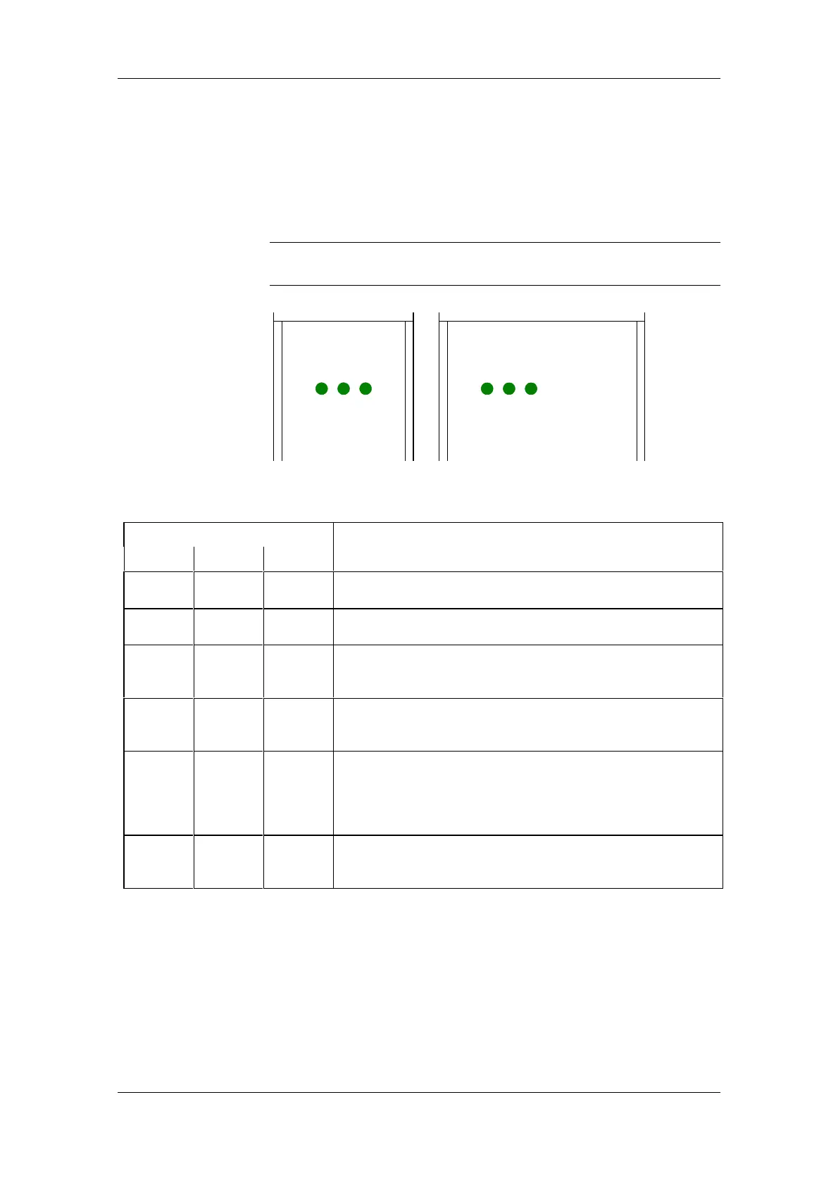
6.2 LED displays
6.2.1 SIMOLINK Encoder status
The status of the SIMOLINK Encoder as regards SIMOLINK addressing
and pulse outputs is indicated via three green LEDs on the front panel.
The status of the SLE-DP encoder module can also be read out via the
PROFIBUS (cf. Section 6.4.6).
SIMOLINK ENCODER SLE-DP
POWER
SYNC
Z-PULSE
SIMOLINK ENCODER
SLE
POWER
SYNC
Z-PULSE
Fig. 6-2
LED Description
POWER SYNC Z-Pulse
Device not connected to supply voltage
No + 24 V supply voltage available
l
Supply voltage connected:
SYNC interrupt is not being received
lDIL switch is incorrectly set:
Address switch is outside permissible range, SYNC and
Z-Pulse LEDs are flashing synchronously
lSIMOLINK cycle time is not defined:
SYNC interrupt is outside 1.6 / 3.2 ms cycle
(251/502 telegram times, dispatcher mode)
llSYNC interrupt is being received in the correct cycle:
SIMOLINK Encoder has not been activated or
setpoint telegram is not being received or
pulse output is not enabled via the control bit or
speed setpoint = 0 is being transmitted
lllDevice is outputting signals
Z-PULSE LED is flashing in synchronism with zero pulse (appears
to be illuminated steadily at high speeds)
LED off
l LED illuminated continuously
LED flashing (approximately twice per second)
Table 6-5 SIMOLINK Encoder operating states
NOTE