SLE / SLE-DP – SIMOLINK Encoder 02.2001 Start-Up
Siemens AG GWE-477 763 4070.76 J
SIMOVERT MASTERDRIVES Operating Instructions 6-17
As long as the logical state of transfer control bit U is ’0’, the value of
the bits for the receive channel and address is irrelevant. The SLE-DP
outputs pulses according to the DIL switches, the last PROFIBUS
activation command and the SIMOLINK data. The transfer of the
receive channel and address from the PROFIBUS output data word is
initiated when the transfer control bit is set to ’1’. At this instant (in the
same PROFIBUS telegram), the receive channel and address must
contain the new value and remain unchanged. The SLE-DP is
deactivated at the same time (no pulse output) and the receive channel
and address defined by the PROFIBUS telegram and DIL switches are
OR’d bit-serially. The operation of changing the receive channel and
address is terminated when the transfer control bit switches from ’1’ to
’0’; the SLE-DP then expects the starting sequence via SIMOLINK (cf.
Section 6.3).
With the reverse significance, the transfer control bit has the same
function as DIL switch S1.5 (cf. Section 6.1.1). This means that
changes to all DIL switches are transferred, i.e. not merely the receive
channel and address OR’d bit-serially with the output data word, but the
number of pulses per revolution and the encoder’s SIMOLINK address
are also transferred again.
As regards the value ranges for receive channel and address in the
PROFIBUS output data word, the same limits apply as to the DIL switch
settings (cf. Sections 6.1.2 and 6.1.3).
If the bit-serial ORing of the PROFIBUS output data word and DIL
switches produces an illegal receive address, the error is indicated by
LEDs on the housing front panel ('SYNC' and 'Z-PULSE’ flash, cf.
Section 6.2.1) and via error bit 5 in the PROFIBUS input data word (see
below.
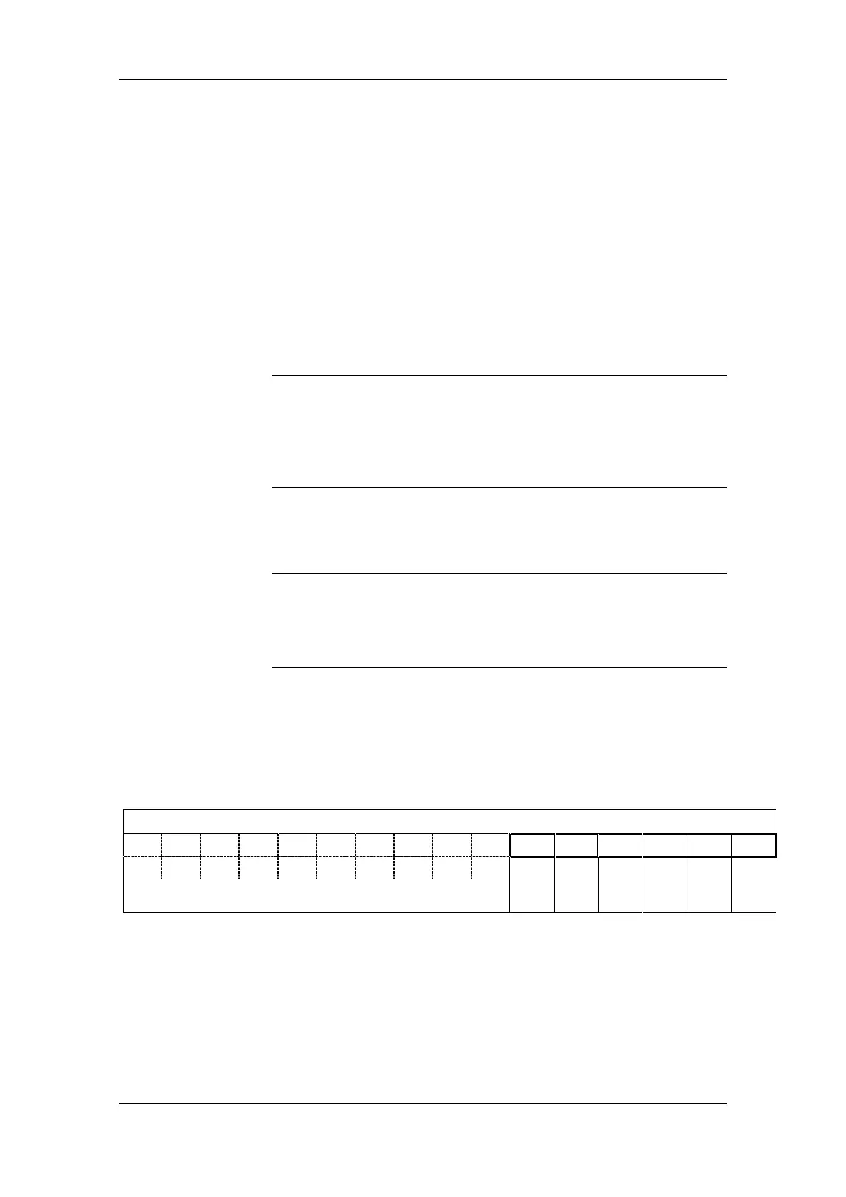
6.4.6 Structure of PROFIBUS input data word
The PROFIBUS input data word (IDW) contains:
4 status bits and 2 error bits (remaining bits have permanent status)
2-byte input data word
15
14 13 12 11 10 9 8 7
6
543210
1111000000
Error bit Error bit Status bit Status bit Status bit Status bit
Reserved, permanent status
Parameter
setting
error
Incorrect
SYNC
cycle
SYNC
monoflop
PULSE
mode
SLE-DP
status
SYNC
toggle
Fig. 6-11 SLE-DP; structure of PROFIBUS input data word
NOTICE
NOTE