Start-Up 02.2001 SLE / SLE-DP – SIMOLINK Encoder
GWE-477 763 4070.76 J Siemens AG
6-16 Operating Instructions SIMOVERT MASTERDRIVES
…
A
=
A
=
A
=
A
=
L
T
L
T
BE
I
F
I
F
I
F
I
F
FW
PQW
PIW
FW
0.4
0.0
0.5
0.1
0.6
0.2
0.7
0.7
0
256
256
2
Fig. 6-9 SLE-DP; Sample program
The important program lines in the example are:
T PQW 256
Write output data word (address change and activation) as
word command and
L PIW 256
Read input data word (status and error bits) as word command.
The word transfer commands ensure that the 2-byte data are
processed consistently.
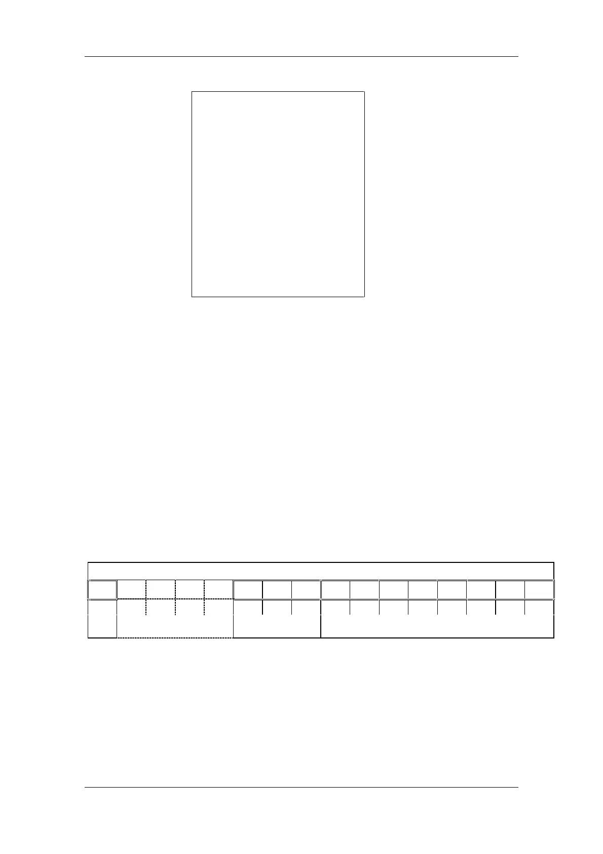
6.4.5 Structure of PROFIBUS output data word
The PROFIBUS output data word (ODW) contains:
8 bits of read address, 3 bits of read channel and 1 bit of transfer
control
2-byte output data word
15 14 13 12 11 10 9 8 7 6 5 4 3 2 1 0
U00002
2
2
1
2
0
2
7
2
6
2
5
2
4
2
3
2
3
2
1
2
0
Control
bit
Reserved
Receive channel Receive address
Fig. 6-10 SLE-DP; structure of PROFIBUS output data word