6.32 Switchover between different settings
In several applications, the inverter must be able to be operated with different settings.
Example:
You connect different motors to one inverter. Depending on the particular motor, the inverter
must operate with the associated motor data and the appropriate ramp-function generator.
Drive data sets (DDS)
Your can parameterize several inverter functions differently and then switch over between the
different settings.
The associated parameters are indexed (index 0 or 1). Via control commands select one of
the two indices and therefore one of the two saved settings.
The settings in the inverter with the same index are known as drive data set.
0
6HWSRLQW
SURFHVVLQJ
0RWRUFRQWURO
6HWSRLQWV
)L[HGVHWSRLQWV
0RWRUL]HGSRWHQWLRPHWHU
-RJJLQJ
%UDNHV
)O\LQJUHVWDUW
6\VWHPSURWHFWLRQ
$SSOLFDWLRQ
VSHFLILF
2YHUFXUUHQW
2YHUYROWDJH
2YHUWHPSHUDWXUH
3URWHFWLRQDQG
PRQLWRULQJ
''6
''6
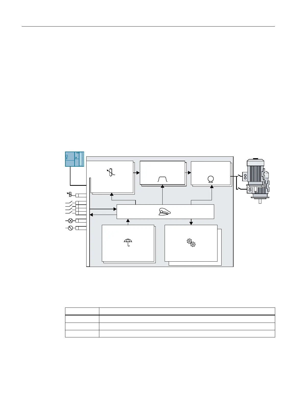
Figure 6-75 DDS switchover in the inverter
You can use parameter p0180 to define the number of drive data sets (1 or 2).
Table 6-57 Selecting the number of drive data sets
Parameter Description
p0010 = 15 Drive commissioning: Data sets
p0180 Drive data sets (DDS) number(factory setting: 1)
p0010 = 0 Drive commissioning: Ready
Advanced commissioning
6.32 Switchover between different settings
SINAMICS G120C converter
318 Operating Instructions, 09/2017, FW V4.7 SP9, A5E34263257B AF

 Loading...


