5
"Parameters" Operating Area 03.04
5.6 Work offset
5
Ó Siemens AG, 2004. All rights reserved
5-242 SINUMERIK 840D/840Di/810D Operator's Guide HMI Advanced (BAD) – 03.04 Edition
5.6 Work offset
5.6.1 Function
Machine/
tool zero
The actual values are referred to the machine zero after a reference
point approach. The machining program of the workpiece refers to the
workpiece zero.
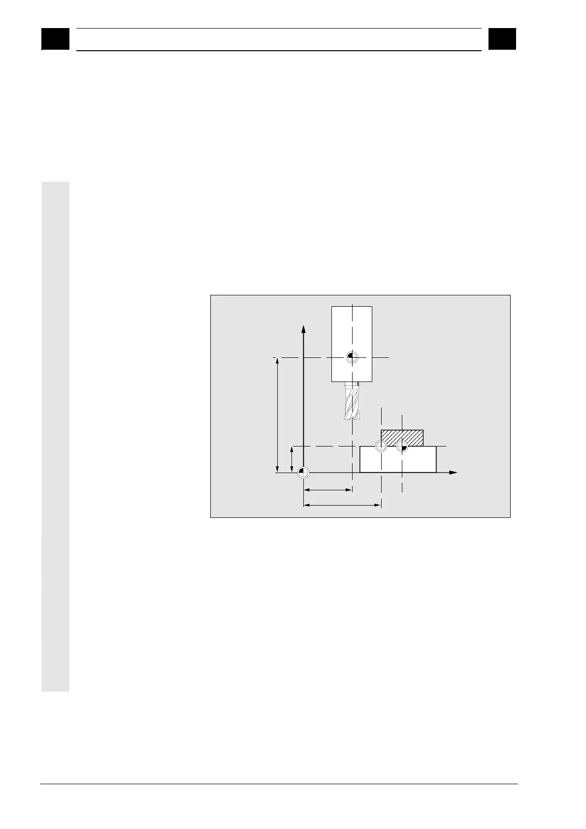
Machine zero and workpiece zero need not be identical. Depending
on the type of workpiece and the way it is clamped, the distance
between the machine zero and workpiece zero can vary. In part
program processing this is compensated for by the work offset.
Work offset on a milling
machine
X
Z
XMR
P
R=F
W
M
ZMW
ZMR
WR
XMW
P
Tool setting point
W
Workpiece zero
F
Slide reference point
XMR, ZMR
Reference point coordinates
XMW, ZMW
Work offset
M
Machine zero
R
Machine reference point
WR
Workpiece reference point
Effective WO
The work offset effective in an axis $P_ACTFRAME=..
resulting from
the sum of the following work offsets:
 Loading...


