Mounting and Commissioning
3.1 Mounting and Connections
SIPROTEC, 7SJ62/64, Manual
C53000-G1140-C207-2, Release date 01.2008
419
Jumper Settings Input/Output Board B-I/O-2
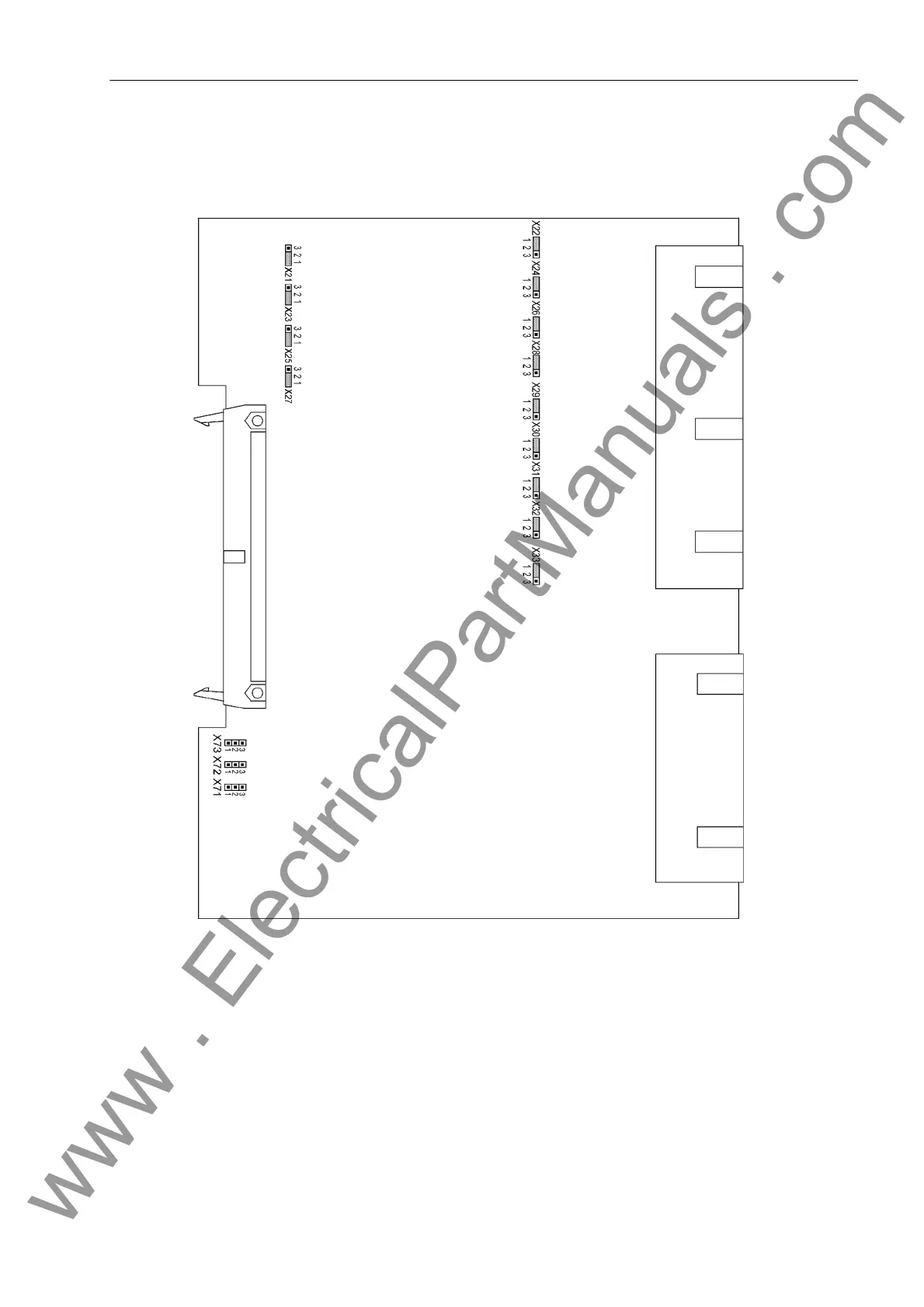
The layout of the PCB for the input/output module B–I/O–2 is illustrated in figure 3-16.
Figure 3-16 Input/output board B-I/O-2 with representation of the jumper settings required for the
board configuration
The selected pickup voltages of the binary inputs BI8 to BI20 (with housing size
1
/
2
) are checked according to
Table 3-20. BI8 to BI33 (with housing size
1
/
1
) are checked according to Table 3-21.
Figures 3-5 and 3-6 illustrate the assignment of the binary inputs to the module slot.
www . ElectricalPartManuals . com

 Loading...


