3 Mounting and Commissioning
366
7UT613/63x Manual
C53000-G1176-C160-2
Table 3-19 Exchange Interface Modules
The ordering number of the replacement modules are listed in the Appendix A.1.
RS232 Interface The RS232 interface can be transformed into a RS485 interface and vice versa, ac-
cording to Figure 3-13.
Figure 3-11 shows the PCB C-CPU-2 with the layout of the boards.
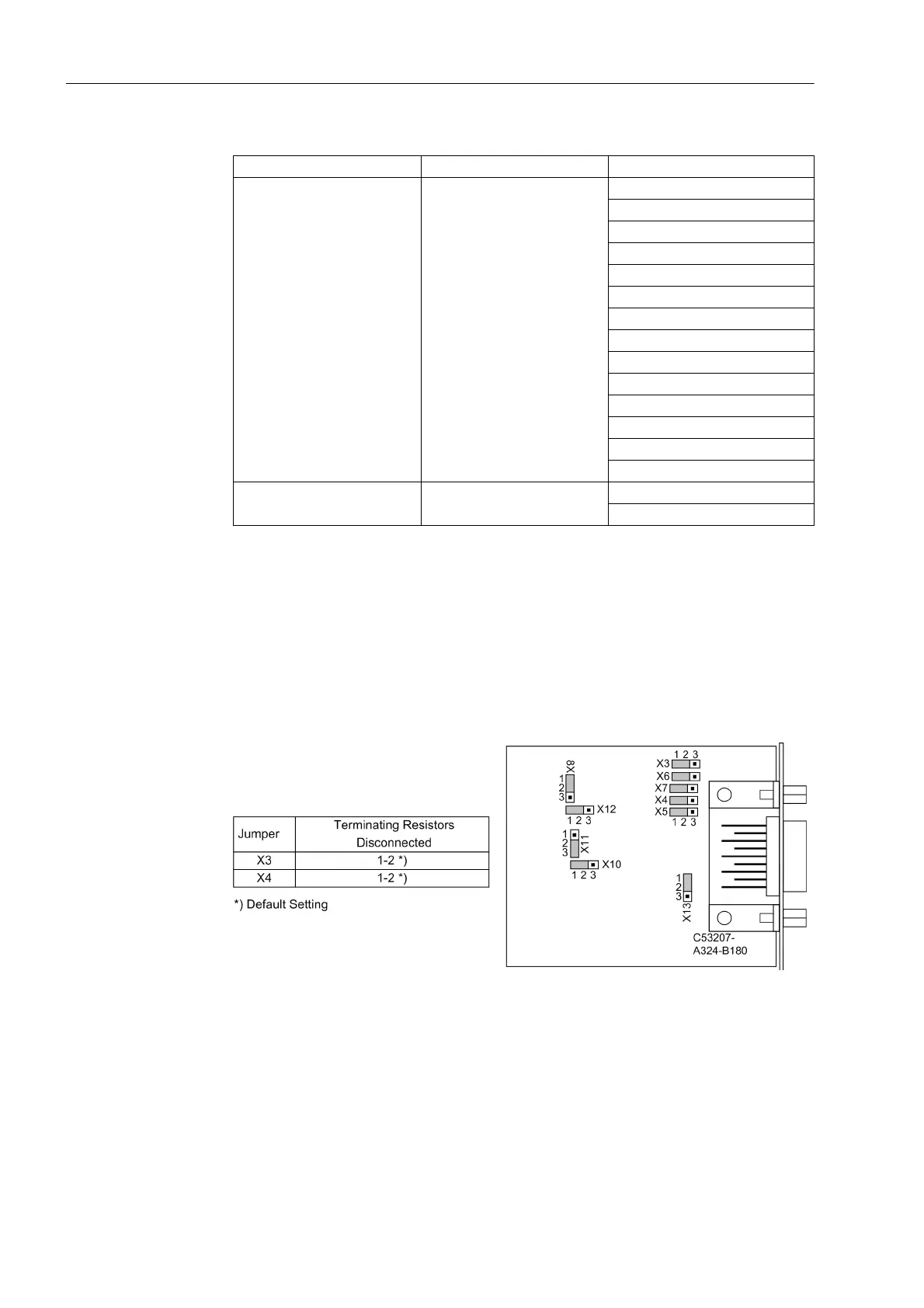
Figure 3-12 shows how jumpers of interface RS232 are located on the interface
module.
Figure 3-12 Location of the jumpers for configuration of RS232
Terminating resistors are not required. They are disconnected.
Please observe that in surface-mounted devices with fibre optics connection the CPU
module is equipped with an RS232 interface module. In this application, the jumpers
X12 and X13 on the RS232 module are set to position 2-3, unlike the arrangement
shown in Figure 3-12.
Interface Mounting location / port Exchange module
System Interface
B
RS232
RS485
FO 820 nm
PROFIBUS FMS RS485
PROFIBUS FMS double ring
PROFIBUS FMS single ring
PROFIBUS DP RS485
PROFIBUS DP double ring
Modbus RS485
Modbus 820 nm
DNP 3.0 RS485
DNP 3.0 820 nm
Ethernet double electrical
Ethernet optical
Additional Interface D
FO 820 nm
RS485
 Loading...


