Operator control and monitoring
7.2 Displays and location of the connections
SIRIUS 3RM1 motor starter
128 Manual, 06/2016, A5E0345285095020A/RS-AE/005
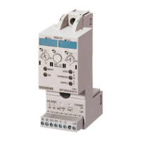
Displays and location of the connections
LED DEVICE (red/green/yellow)
Rotary coding switch for the rated operational current "I
e
" of the load
TEST/RESET/RESET MODE button
Data matrix code for unique identification of the 3RM1 motor starter
Control circuit control supply voltage (A1, A2)
Control circuit start input direction of rotation 1 (IN1) and start input direction of rotation 2 (IN2;
on 3RM12 and 3RM13 reversing starters only)
Control circuit fault signaling output (95,96,98)
Control circuit signaling output OUT (only on Standard motor starters with 24 V DC rated
control voltage) 3RM10 .-...0. and 3RM12.-...0.)
Control circuit RESET input (IN3) in the case of 3RM10/3RM12 Standard motor starters
Ground inputs (M1, M2) in the case of Failsafe motor starters with a 24 V DC control supply
voltage (3RM11.-...0. and 3RM13.-...0.); M2 only in the case of Failsafe reversing starters with
a 24 V DC control supply voltage (3RM13.-...0.)
Main circuit outgoing load feeder (T1, T2, T3)
Main circuit infeed (L1, L2, L3)
Figure 7-2 Front elements of the 3RM1 motor starter

 Loading...