Configuration
4.5 Ambient conditions
SIRIUS 3RM1 motor starter
68 Manual, 06/2016, A5E0345285095020A/RS-AE/005
No grounding measures are required for the 3RM1 motor starter.
Permissible operating voltage
To be able to ensure safe isolation of the circuits from each other in accordance with IEC
60947-1, the following operating voltages are permissible:
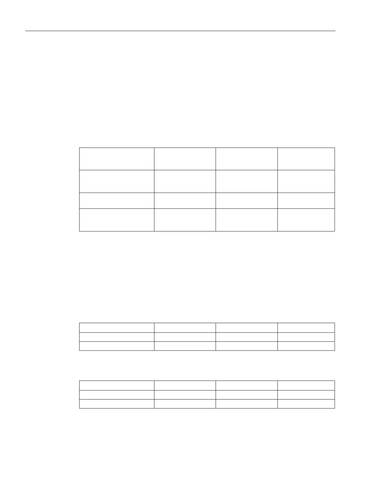
Table 4- 2 Safe isolation of the 3RM1 motor starters
... to ...
Control circuit
(A1/A2, OUT, IN1-3,
M1/M2)
Signaling contacts
(98/95/96)
Main circuit
(1L1/3L2/5L3
2T1/4T2/6T3)
Control circuit
(A1/A2, OUT, IN1-3,
M1/M2)
- 250 V 500 V
Signaling contacts
(98/95/96)
250 V - 500 V
Main circuit
(1L1/3L2/5L3
2T1/4T2/6T3)
500 V 500 V -
The minimum load current is 20% of the set motor current, but at least the absolute minimum
current specified in the tables below.
The minimum load current differs in the case of Standard 3RM10/3RM12 and Failsafe
3RM11/3RM13 motor starters:
Table 4- 3 Minimum load current in the case of Standard 3RM10/3RM12 motor starters
Table 4- 4 Minimum load current in the case of Failsafe 3RM11/3RM13 motor starters
As soon as the minimum current limit is violated, fault detection (phase failure) picks up.

 Loading...