Operator control and monitoring
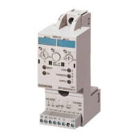
7.2 Displays and location of the connections
SIRIUS 3RM1 motor starter
130 Manual, 06/2016, A5E0345285095020A/RS-AE/005
Depending on the version of the 3RM1 motor starter, the device will have the following
connections:
Inscription of the terminal cover
Control circuit (at the top of the device)
•
• Direct-on-line starter 3RM10.-...0. (IN1)
• Reversing starter 3RM12.-...0. (IN1 and IN2)
•
• Direct-on-line starter 3RM10.-...1. (IN1)
• Reversing starter 3RM12.-...1. (IN1 and IN2)
•
• Direct-on-line starter (3RM11.-...0.) (IN1, M1)
• Reversing starter (3RM13.-...0.) (IN1 and IN2,
M1 and M2)
•
• Direct-on-line starter 3RM11.-...1. (IN1)
• Reversing starter 3RM13.-...1. (IN1 and IN2)
Main circuit (at the bottom of the device)
)
IN2 only in the case of reversing starters (3RM12 and 3RM13)
)
M2 only in the case of Failsafe reversing starters (3RM13)

 Loading...