Table of contents
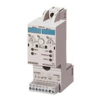
SIRIUS 3RM1 motor starter
8 Manual, 06/2016, A5E0345285095020A/RS-AE/005
8 Service and maintenance ..................................................................................................................... 135
8.1 Maintenance and service ..................................................................................................... 135
8.2 Test interval for safety-related applications ......................................................................... 135
8.3 Device replacement ............................................................................................................. 136
8.4 Replacing the fuses in the 3RM19 fuse module .................................................................. 137
9 Technical data ..................................................................................................................................... 139
9.1 General technical data ......................................................................................................... 139
9.2 General safety data .............................................................................................................. 140
9.3 ATEX-specific safety data .................................................................................................... 140
9.4 Connection cross sections ................................................................................................... 141
9.5 Technical data in Siemens Industry Online Support ............................................................ 143
9.6 Number of starting operations .............................................................................................. 144
9.7 Overload protection/device protection characteristic ........................................................... 145
10 Dimension drawings ............................................................................................................................. 149
10.1 CAx data .............................................................................................................................. 149
10.2 Dimension drawings for 3RM1 device connectors ............................................................... 150
10.3 3RM1 dimension drawings ................................................................................................... 154
10.4 Dimension drawings 3RM19 fuse module ........................................................................... 157
11 Circuit diagrams ................................................................................................................................... 159
11.1 CAx data .............................................................................................................................. 159
11.2 3RM10 circuit diagrams (direct-on-line starter, Standard) ................................................... 160
11.3 3RM11 circuit diagrams (direct-on-line starter, Failsafe) ..................................................... 162
11.4 3RM12 circuit diagrams (reversing starter, Standard) ......................................................... 163
11.5 3RM13 circuit diagrams (reversing starter, Failsafe) ........................................................... 165
A Typical circuits ..................................................................................................................................... 167
A.1 Typical circuits for 3RM1 ...................................................................................................... 167
A.1.1 Direct-on-line starter 24 V DC with switch operation ........................................................... 167
A.1.2 Direct-on-line starter 24 V DC with switch operation and 230 V brake................................ 168
A.1.3 Direct-on-line starter 24 V DC with switch operation and 400 V brake................................ 169
A.1.4 Direct-on-line starter 24 V DC with switch operation and single-phase motor .................... 170
A.1.5 Direct-on-line starter with group protection, 24 V DC and PLC operation ........................... 171
A.1.6 Reversing starter 24 V DC with PLC operation ................................................................... 173

 Loading...