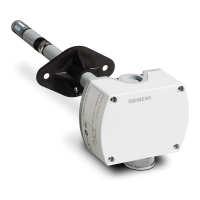
4. Calculate the compensating resistance:
Use the following formula:
R
c
om
p
Determined compensation resistance, to be connected in the signal cable SIG+
R
o
Output resistance of the load cells; can also be measured under load
L
er
r
Weight error: Dierential value from the lowest weight value
L
te
st
Test load; placed on all four corners
N
LC
Number of load cells in the scale
Figure 6-3 Formula for corner load adjustment
Example calculation:
Load cells Example values
Calculation Results for R
comp
LC 1: R
comp
= R1 = 1004.52 Ω x 12 kg /
150 kg
approx. 80 Ω
LC 2: -
1)
-
1)
LC 3: R
comp
= R3 = 1010.70 Ω x 7 kg / 150 kg approx. 47 Ω
LC 4: R
comp
= R4 = 1028.12 Ω x 4 kg / 150 kg approx. 27 Ω
1)
Smallest value: No resistance necessary
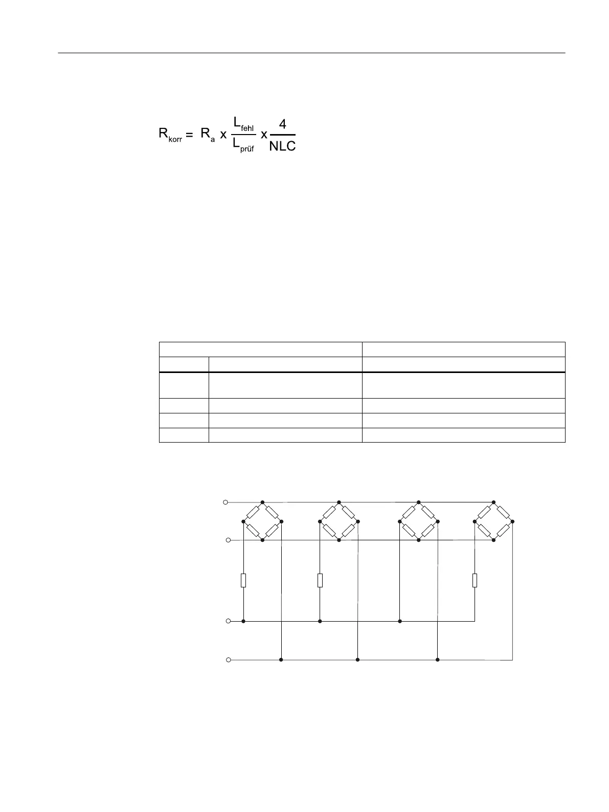
5. Install the calculated resistances:
(;&'&9
(;&'&9
/&
(;&
/&
(;&
/&
(;&
/&
(;&
(;&(;&(;&(;&
6,*
6,*
6,*6,*6,*6,*6,*6,*6,*
6,*
5
˖
5
˖
5
˖
Figure 6-4 Circuit diagram for corner load adjustment
6. Repeat the test.
Commissioning
6.3 Adjustment and initial commissioning
SIWAREX WL200
Operating Instructions, 12/2021, A5E02199611B-13 41

 Loading...