Connecting-up 05.2006
6SE7087-2JD60 Siemens AG
7-16 Operating Instructions SIMOVERT MASTERDRIVES
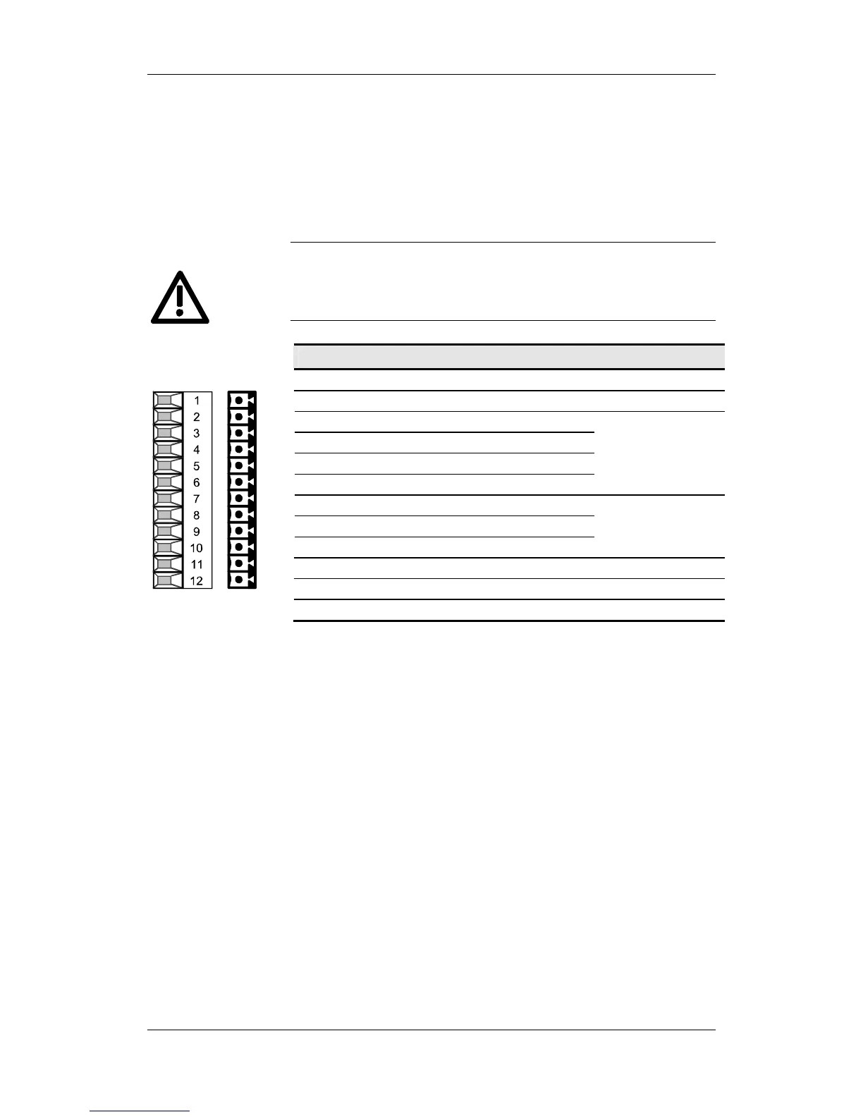
The following connections are provided on the control terminal strip:
♦ 4 optionally parameterizable digital inputs and outputs
♦ 3 digital inputs
♦ 24 V aux. voltage supply (max. 150 mA) for the inputs and outputs
♦ 1 serial interface SCom2 (USS / RS485)
If the digital inputs are supplied by an external 24 V voltage supply, it
must be referred to ground terminal X101.2. Terminal X101.1 (P24
AUX) must not be connected to the external 24 V supply.
Terminal Designation Meaning Range
1 P24 AUX Aux. voltage supply DC 24 V / 150 mA
2 M24 AUX Reference potential 0 V
3 DIO1 Digital input/output 1
4 DIO2 Digital input/output 2
5 DIO3 Digital input/output 3
6 DIO4 Digital input/output 4
24 V, 10 mA / 20 mA;
L
≤ 3 V, H ≥ 13 V
7 DI5 Digital input 5
8 DI6 Digital input 6
9 DI7 Digital input 7
24 V, 10 mA;
L
≤ 3 V, H ≥ 13 V
10 RS485 P USS bus connection SCom2 RS485
11 RS485 N USS bus connection SCom2 RS485
12 M RS485 Reference potential RS485
Connectable cross-section: 0.14 mm
2
to 1.5 mm
2
(AWG 16)
Terminal 1 is at the top when installed.
Table 7-6 Control terminal strip X101
X101 – Control
terminal strip
WARNING