05.2006 Connecting-up
Siemens AG 6SE7087-2JD60
SIMOVERT MASTERDRIVES Operating Instructions 7-17
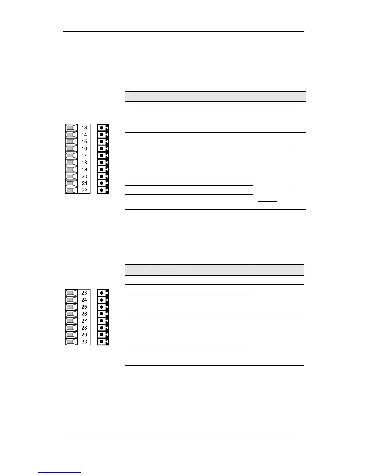
The following connections are provided on the control terminal strip:
♦ 10 V aux. voltage (max. 5 mA) for the supply of an external
potentiometer
♦ 2 analog inputs, can be used as current or voltage input
♦ 2 analog outputs, can be used as current or voltage output
Terminal Designation Meaning Range
13 P10 V
+10 V supply for ext.
potentiometer
+10 V
±1.3 %,
Imax = 5 mA
14 N10 V
-10 V supply for ext.
potentiometer
-10 V
±1.3 %,
Imax = 5 mA
15 AI1+ Analog input 1 + 11 bit + sign
16 M AI1 Ground, analog input 1 Voltage:
17 AI2+ Analog input 2 + ± 10 V / Ri = 60 kΩ
18 M AI2 Ground, analog input 2 Current: Rin = 250 Ω
19 AO1 Analog output 1 10 bit + sign
20 M AO1 Ground, analog output 1 Voltage:
21 AO2 Analog output 2 ± 10 V / Imax = 5 mA
22 M AO2 Ground, analog output 2
Current:
0...20 mA
R
≥ 500 Ω
Connectable cross-section: 0.14 mm
2
to 1.5 mm
2
(AWG 16)
Terminal 13 is at the top when installed.
Table 7-7 Control terminal strip X102
The connection for a pulse encoder (HTL unipolar) is provided on the
control terminal strip.
Terminal Designation Meaning Range
23 - V
SS
Ground for power supply
24 Track A Connection for track A
25 Track B Connection for track B
26 Zero pulse Connection for zero pulse
27 CTRL Connection for control track
HTL unipolar;
L
≤ 3 V, H ≥ 8 V
28 + V
SS
Power supply pulse
encoder
15 V
Imax = 190 mA
29 + Temp
Plus (+) connection
KTY84/PTC
KTY84: 0...200 °C
30 - Temp
Minus (-) connection
KTY84/PTC
PTC: R
cold
≤ 1.5 kΩ
Connectable cross-section: 0.14 mm
2
to 1.5 mm
2
(AWG 16)
Terminal 23 is at the top when installed.
Table 7-8 Control terminal strip X103
X102 – Control
terminal strip
X103 – Pulse
encoder connection