05.2006 Parameterizing Steps
Siemens AG 6SE7087-2JD60
SIMOVERT MASTERDRIVES Operating Instructions 9-19
87654321
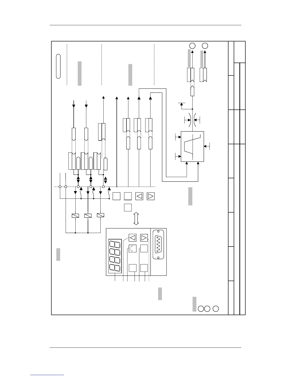
Setpoint source
MASTERDRIVES VCPMU and MOP (P368=0)
- s0 -
Accel Time MOP
P431
P443.B (58)
KK
Src Main Setp
MOP(Outp)
r424
P425
Conf.MOP
KK058
MOP(Outp)
P
I O
Toggle key (acknowledge)
B0005
P554.1 (5)
B
ON/OFF1 Src ON/OFF1
B0008
P573.1 (8)
B
Raise MOP
B0009
P574.1 (9)
B
Lower MOP
Src Raise MOP
Src Lower MOP
P486.B (58)
KK
Src.T Setp
(for T control)
Decel Time MOP
P432
MOP (max)
P421
P422
MOP (min.)
0xx0 = ... without storing after OFF
0xx1 = ... Storing after OFF
I
O P
X300
Seven segment display
ON key
OFF key
Toggle key
Reversing key
Raise key
Lower key
Terminal strip
PMU
MOP
Note:
The keys "Raise MOP" and "Lower MOP"
are only effective if the operating display
(r000) is selected.
Sh. [90]
Sh.[50]
Sheet [300]
to sheet [180]
from sheet [200]
P48 PMU Operating Display
Explanations:
Sh. [300]
: See Compendium Sheet 300
to sheet [316.1]
to sheet [320.1]
N
M
: Reference to N-controller (see r
XX
-sheets)
N
M : Reference to T-controller (see r
XX
-sheets)
1
: Reference to the current path sheet "a0"
"Analog outputs and display variables"
n959.81 = 4
If used as digital inputs, the parameters
P651.B, P652.B, P653.B and P654.B have
to be set to 0!
If used as digital outputs, B10 to B14 must
not be wired.
*
)
If P366 = 3
P590 = B0012
P651 = B0000
P652 = B0000
P653 = B0107
/5
/4
/3
/2
/1
B0014
P653.1 (0)
B
B0012
P652.1 (104)
B
B0010
P651.1 (107)
B
M24
P24
-X101
B0104
B0107
operation
0=fault
*
)
*
)
1=operation
no fault
*
)
P590 (14)
B
Src BICO DSet
Not valid for Compact PLUS!