05.2006 Parameterizing Steps
Siemens AG 6SE7087-2JD60
SIMOVERT MASTERDRIVES Operating Instructions 9-21
87654321
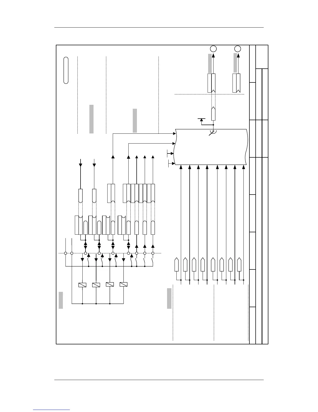
Setpoint source
MASTERDRIVES VCFixed setpoints and terminal strip (P368=2)
- s2 -
B0016
B0018
B0020
B0022
P581.1 (16)
B
P567.1 (18)
B
P555.1 (20)
B
P554.1 (22)
B
Src FSetp Bit 1
Src3 Acknowledge
Src ON/OFF1
/6
/7
/8
<1>
KK0046
KK0045
KK0047
KK0048
KK0040
Act.FSetp
Active FSetp
r420
P443.B (40)
KK
Src Main Setpoint
P486.B (40)
KK
Src T setpoint
0 1 0 0
0 1 0 1
0 1 1 0
0 1 1 1
FSetp
Bit 3
P418.B
FSetp
Bit 2
P417.B
0 0 0 0
0 0 0 1
0 0 1 0
0 0 1 1
KK0042
KK0041
KK0043
KK0044
(for T control)
Fixed setpoint1
P401.F
Fixed setpoint2
P402.F
Fixed setpoint3
P403.F
Fixed setpoint4
P404.F
Fixed setpoint5
P405.F
Fixed setpoint6
P406.F
Fixed setpoint7
P407.F
Fixed setpoint8
P408.F
in %
in Hz
Fixed setpoints
Sheet [290]
P654.1
B
Src1 OFF2
Terminal strip
Sheet[90]
/5
/4
/3
/2
/1
B0014
P653.1
B
B0012
P652.1
B
B0010
P651.1
B
M24
P24
-X101
P580.1 (14)
B
Src.FSetp Bit 0
B0104
B0107
operation
0=fault
*
)
*
)
*
)
If used as digital inputs, the parameters
P651.B, P652.B, P653.B and P654.B have
to be set to 0!
If used as digital outputs, B10 to B14 must
not be wired.
*
)
1=operation
no fault
*
)
from sheet [200]
to sheet [180]
to sh. [316.1]
to sh. [320.1]
N
M
n959.83 = 4
<1> Compact/Chassis type unit:
Compact PLUS type unit:
Terminal X101/9
Terminal X102/19