Control Word and Status Word 05.2006
6SE7087-2JD60 Siemens AG
10-10 Operating Instructions SIMOVERT MASTERDRIVES
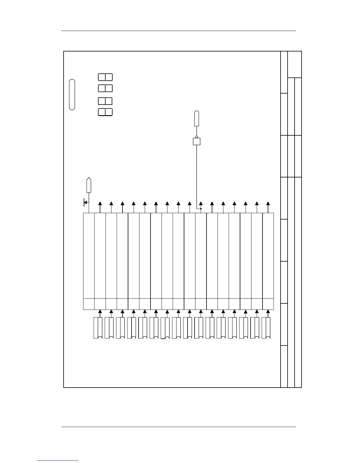
Function diagram
87654321
Control word 2
MASTERDRIVES VC
- 190 -
Bit 17
Bit 18
Bit 19
Bit 20
Bit 21
Bit 22
Bit 23
Bit 24
Bit 25
Bit 26
Bit 27
Bit 28
Bit 29
Bit 30
Bit 31
Select fixed setpoint bit 0
Meaning
Select fixed setpoint bit 1
Select motor data set bit 0
Select motor data set bit 1
Select fixed setpoint bit 0
Select fixed setpoint bit 1
1= Enable synchronizing
0=Synchronizing disabled
1=Enable flying restart
0=Flying restart disabled
1=Enable droop, speed controller
0=Droop, speed controller disabled
1=Enable speed controller
0=Speed controller disabled
0=External fault 2
1=No external fault 2
0=Master drive (speed control)
1=Slave drive (torque control)
0=External alarm 1
1=No external alarm
1
0=External alarm 2
1=No external alarm 2
0=No checkback, waiting time P600 active
1=Checkback main contactor
0=Select BICO data set 1
1=Select BIC data set 2
P576.B (0/0)
B
Src FuncDSetBit0
P579.B (0/0)
B
Src MotDSet Bit1
P580.B (0/16)
B
Src FixSetp Bit0
P581.B (0/0)
B
Src FixSetp Bit1
P583.B (0/0)
B
Src Fly Release
P585.B (1/1)
B
Src n-Reg Rel
P586.B (1/1)
B
Src No ExtFault2
P587.B (0/0)
B
Src Master/Slave
P588.B (1/1)
B
Src No Ext Warn1
P590.B (14)
B
Src BICO DSet
P591.B (0/0)
B
Src ContactorMsg
P589.B (1/1)
B
Src No Ext Warn2
to data sets [540.4]
to data sets [540.4]
to data sets [540.4]
to data sets [540.4]
to fixed setpoints [290.6]
to fixed setpoints [290.6]
to speed control
to fixed setpoints
to sequence control 1)
to speed control [365.7], [367.4]
to speed control [360.5], [361.5]
to sequence control 1)
to alarm processing
to sequence control 1)
to alarm processing
to sequence control 1)
Control word 2
r551
K0031
Control word 2
•
Display of r551 on the PMU
3031 29 28 27 26 25
24
1617181920212223
Bit No.
Bit 16
P577.B (0/0)
B
Src FuncDSetBit1
P578.B (0/0)
B
Src MotDSet Bit0
P584.B (0/0)
B
Src Droop Rel
to sequence control 1)
to fault processing
to data sets [540.4]
Separate function diagrams are available for
master and slave drive control!
The sequence control is the internal
control (software) for realizing the
drive status (r001).
1)
P582.B(5002)
B
Src Sync Release
to synchronization [X02]
1
B0099
No.n-Reg Rel
Pre-assignment of the BICO parameters:
1. Binector valid for BICO data set 1
2. Binector valid for BICO data set 2
n959.26 = 4