Do you have a question about the Sigicom INFRA C12 and is the answer not in the manual?
Overview of the INFRA monitoring system architecture.
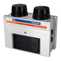
Introduction to the INFRA C12 as a complete wireless vibration monitor.
How data is sent to a server via GSM/Internet.
Instructions for unpacking and identifying the components of the C12.
Description of the two buttons (B1, B2) and their functions.
Explanation of the three LEDs (Comm, Check, Reg) and their meanings.
Details about the GSM antenna and dummy antenna.
Information about the two Li-Ion battery modules and replacement.
Functionality and conditions for the built-in solar panel.
Options for powering and charging the C12 via an external port.
Primary use of the USB connector for firmware upgrades.
Details on the CompactFlash card requirements and usage.
Requirements for the SIM card for GSM communication.
Details on vibration sensor, analog electronics, ADC, and DSP.
Explanation of measurement standards and interval measurements.
How frequency, weighting, and trigger filters affect measurements.
Process of initiating and recording transient events.
How analog or digital overload conditions are flagged.
Description of event, interval, and transient file types.
Details on event files used for troubleshooting and system information.
Information on interval files containing data samples over time.
Explanation of transient files generated upon system triggering.
Structure and management of data files stored on the CompactFlash.
Overview of essential settings for C12 operation.
Setting automatic data server connection times.
Configuration of GSM modem and data server connection parameters.
Setting Project ID and Node ID text for data files.
How to disable GSM function by creating a 'conntype.txt' file.
Configuration of SMS receivers and message types.
Using INFRA Net Messages for data transmission.
Real-time data presentation via INFRA Net Live.
Details of the factory default configuration settings.
Guidelines for mounting the C12 instrument.
Procedure for powering on and the initial startup sequence.
How to manually set the C12 into monitoring mode.
Performing a sensor test to verify functionality.
How to manually stop the monitoring process.
General explanation of the data server connection process.
Initiating data server connection automatically after certain events.
Performing a data server connection manually.
Procedure for turning off the C12 instrument.
Behavior of the C12 when power is lost or batteries are depleted.
Using INFRA Net for remote control and parameter changes.
How to prevent transient files from being uploaded.
Setting up the C12 to synchronize its clock via NTP.
Automatic transition between DST and standard time.
Disabling file archiving to prevent the CompactFlash from filling up.
Details on enclosure, weight, memory, battery, power, runtime, antennas.
List of available spare parts and optional kits.
Specifications for compatible external antennas.
Recommended calibration intervals and sensitivity to shock.
Instructions for firmware updates and desiccant bag maintenance.
Addresses, phone numbers, and web links for Sigicom support.
Table detailing battery voltage limits and related LED indications.
Conditions under which battery charging is initiated.
A list of configuration files and their purpose.
Regulations and precautions for air transporting Li-Ion batteries and equipment.
Recommendations for safe handling and fire prevention of Li-Ion batteries.
Steps to take in case of a Li-Ion battery fire.
Template for operator confirmation of safety and handling instructions.
Explanations of frequency characteristics and weighting models.
Summary of measurement standards S01 through S18.
Summary of measurement standards S19 through S37.
Summary of measurement standards S38 through S56.
Detailed specifications for SS 460 48 66 Spräng standard.
Detailed specs for ISO 8569 and SS 460 48 61 Komfort standards.
Detailed specifications for DIN 4150-3 standards.
Detailed specs for ÖNORM S 9012 and ISO 10816-2 standards.
Detailed specs for DIN 4150-3 and NS 8141 standards.
Detailed specifications for NS 8141-1 standards.
Detailed specs for ISO 2631-2 and SN 640312a standards.
Detailed specs for ANSI S2.71, BS 7385, AS 2187.2-2006, Particle displacement.
Detailed specs for Particle displacement and ÖNORM S 9020 standards.
Detailed specs for ICPE-Circ86, IN 1226, OfM 9/1997, Turkey – Mining and Quarry.
Detailed specs for ISEE Seismograph and ISEE/USBM standards.
Table of weighted standards (S18, S19, S28, S29, S40).
Table of weighted standards (S41).
Table of weighted standards (S42, S43).
Example of configuring DIN 4150-3 with Zeile 1 and its graphical representation.
Explanation of the weighting curve for DIN 4150-3, Zeile 1.
Graphical representation of the weighting curve for Zeile 2.
Graphical representation of the weighting curve for Zeile 3.
Explanation of Drywall and Plaster trigger filter versions and levels.
Examples illustrating trigger level adjustments for Drywall filter.
Examples illustrating trigger level adjustments for Plaster filter.