Installation
20222410 / B 5
Pay particular attention to the distribution unit/steering gear
combinations on page 13 and the cable length and number of
Robnet units on page 32.
As many of the units are communicating on a common network
(Robnet) with identical connectors, the installation is simplified.
Mount the units within the standard cable length supplied with
each unit, if possible (refer to Technical Specifications, section
5, beginning on page 95. Robnet Extension Cable (10m) is
available from your Simrad distributor. Refer to the Spare Parts
List on page 95 for part numbers.
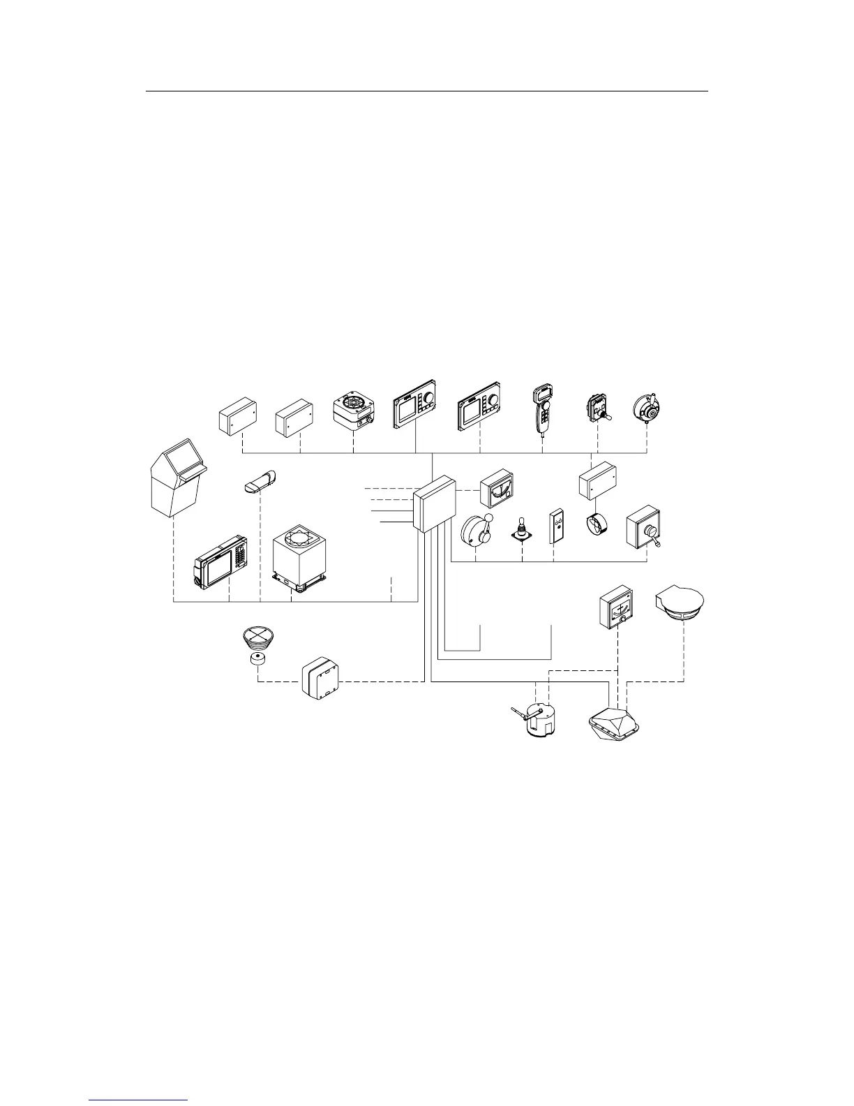
2.5 AP50 Plus System Layout
PANORAMA
MK2
STEERING
GEAR 1
ELECTRONICS
STEERING
GEAR 2
ELECTRONICS
SYSTEM SELECT
RF14XU
S9
RI35 MK2
QS50
RI9
RC25
GYRO
COMPASS
RF45X
JS10
AP51
AP50
CDI35
NMEA DATA
EXT. ALARM
CD100A
AP50
S35
HS5X
3- or 4-WIRE
ELECTRONIC
CHART
SYSTEM
FU50
BOAT'S
MAGNETIC
COMPASS
NI300X
GPS/
CHART
PLOTTER
NON
SIMRAD
COMPASS
RADAR CLK/DATA
2-WIRE FREQ.
ROBNET
TI51
JD5X
R3000X
GI51
2-WIRE FREQ.
24VDC MAINS
Figure 2-1 AP50 Plus system with options
Notes! The plus system layout does not show all possible layouts.
With analog steering gear interface (JD53) the rudder feedback
(RF45X, RF14XU) are not required.