Simrad AP50 Autopilot
10 20222410 / B
Final check
After installation, the cable glands must be sealed with silicon to
prevent water from seeping in. Also apply silicon grease to the
gasket between the bottom and top cover.
On the inside of the feedback unit cover, a piece of moisture
protecting sponge is attached. The sponge produces a corrosion
preventive gas, and to increase the efficiency of the gas the
cover must be kept tight.
2.7 RF45X Rudder Feedback Unit
(The RF45X can be used instead of RF14XU when limit
switches are not required).
The RF45X Rudder Feedback Unit is normally installed with the
shaft pointing upwards. However, it can be mounted with the
shaft pointing downwards for increased convenience. The
deflection can then be inverted in the AP50 software or as
illustrated in Figure 2-7 on page 11. An “upside-down”
installation will make access to the unit more efficient as it can be
opened without moving it from the mounting base. To open the
unit, unscrew the two screws of the unit and remove the cover.
Be careful not to damage the wires when you replace the cover.
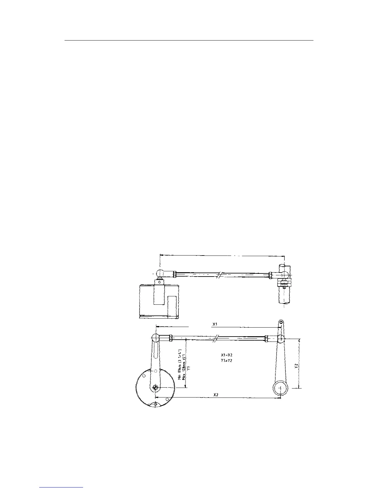
Max 600mm (23,5")
Figure 2-6 RF45X Rudder Feedback Unit Mounting