Installation
20222410 / B 13
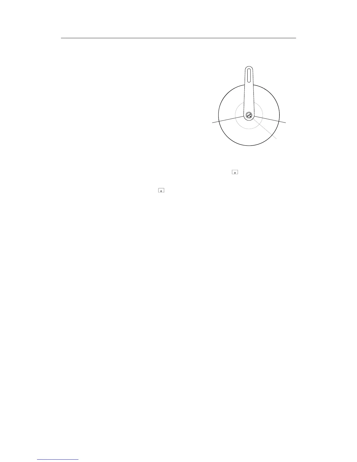
Mechanical Alignment
The purpose of this procedure
is to find the zero point and to
allow the feedback unit to
operate within its active
segment. If the unit operates
outside this segment, there will
be a feedback failure alarm.
1. Position the rudder
amidships.
2. Loosen the two screws that
secure the transmission
lever to the RF45X shaft.
F
e
e
d
b
a
c
k
f
a
i
l
u
r
e
z
o
n
e
A
c
t
i
v
e
s
e
g
m
e
n
t
Slot
3. Turn on the autopilot by pressing the
STBY
(STBY) button and
wait until the start-up sequence is finished.
4. Press the
STBY
(STBY) button again, if necessary, to read the
rudder angle display. You may also read the rudder angle by
accessing the User Set-up menu (see Operator Manual) and
the SYSTEM DATA menu (page 79).
5. Use a flat screwdriver in the slot and adjust the rudder angle
to zero degrees on the display.
6. Secure the transmission lever to the shaft. Return to the
Dockside settings and proceed to ‘Rudder Feedback
Calibration’.
Note ! If the autopilot presents a Rudder Feedback Alarm after “turn
on”, proceed as follows:
• Turn the autopilot off. Use a flat screwdriver in the slot and
turn the shaft 180°.
Proceed from item 3 above.
2.8 JD5X distribution units
General
The following versions of JD5X distribution units are available:
JD50 Distribution unit (P/N 20126819)
JD50 provides solid state switching (ON/OFF) of two
independent sets of directional valve solenoids, 19-40V DC, 3A.
The unit includes the following circuit boards:
- J50 Power Board .......................................... P/N 20212528
- J50 Main Board............................................ P/N 20211918