Simrad AP50 Autopilot
54 20222410 / B
Drive Unit Voltage
The Drive unit voltage setting does not apply when operating
solenoids on a continuous running pump/steering gear. Hence,
the output voltage to the solenoids will be the same as the input
voltage.
Note ! If the Drive Engage port (TB6) on the Power Board is used, the
port voltage is the same as the selected Drive Unit Voltage (ref.
page 84.
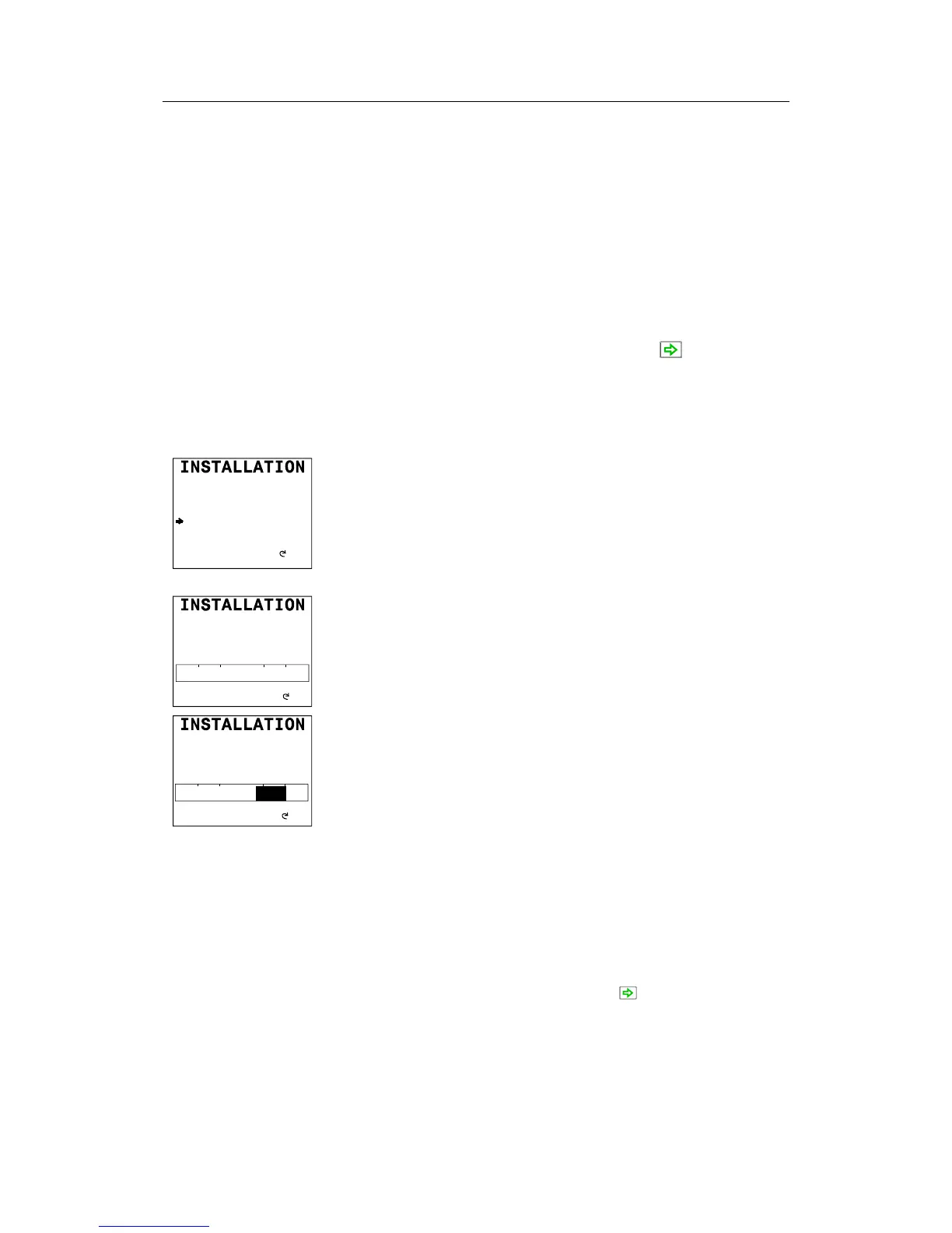
Proceed to the next menu item by pressing the (STBD)
button.
Rudder Feedback Calibration
(Applies for JD50, JD51 and JD52 distribution units)
DOCKSIDE
Master operation Yes
Boat type Displacement
Boat length 0-50 FEET
Drive unit voltage 12V
Rudd feedb cal STBD ---
Rudd feedb cal PORT ---
No
Yes
Make sure the rudder feedback unit is installed and aligned as pr.
instructions in section 2.6 (RF14XU) or 2.7 (RF45X) before
attempting the Rudder feedback calibration.
This function enables you to compensate for non-linearity in the
mechanical transmission between the rudder and the rudder
feedback unit.
DOCKSIDE
Turn Rudder max. STBD
00
P S
00
Adjust?
Select Rudder feedback calibration STBD by turning the
course knob clockwise. “Turn Rudder max STBD” will be
displayed on the screen.
Manually turn the helm wheel to starboard until the rudder stops
at maximum starboard rudder.
DOCKSIDE
Turn Rudder max STBD
25
P S
25
Adjust?
The value shown on the display is the value read by the feedback
unit before any adjustment is made. The bargraph indicates to
which side the rudder is positioned. Be sure to set the correct
rudder angle and direction by turning the course knob. The
autopilot uses this value as physical stop. Physical stop minus 2°
will be used as “max. rudder limit” and determines how far the
autopilot can under any circumstance, drive the rudder.
Note ! If the rudder feedback unit is mounted upside down, the
displayed rudder angle may be to the opposite side before you
start the adjustment (arrow pointing to Port). In this case, turn
the course knob starboard until the rudder angle indicator
displays the correct starboard value.
Advance to the next step by pressing the (STBD) button.
Manually turn the helm wheel to port until the rudder stops at
maximum port rudder.
Adjust the displayed angle the same way as for starboard
adjustment (if the rudder feedback unit is upside down, you need
not correct for the opposite side this time).