Simrad AP50 Autopilot
20 20222410 / B
D9X Solid State Board
The D9X Solid State Board is designed for connection to limit
switches. Normally each set of solenoids (Port – stbd.) will have
one set of limit switches, and the RF14XU Feedback Unit
includes two individual set of limit switches.
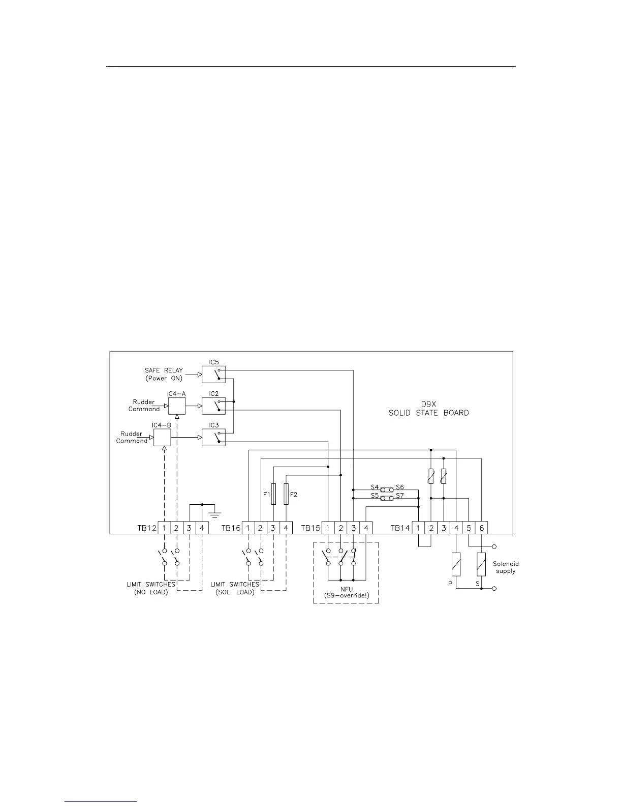
Figure 2-15 shows a simplified functional diagram of the D9X
Solid State Board. There are two options for connection of limit
switches, either at TB16 or at TB12. On TB12 the limit switches
determine the on-off function of the optocouplers IC4-A and
IC4-B and hence represent minimum load and corresponding
voltage drop along the cables to the feedback unit. On TB16 the
limit switches and cables carry the full load of the solenoids and
may represent a critical voltage drop.
If no limit switches are required, make sure the terminals are
jumpered as shown on Figure 2-12.
Several LEDs are mounted on the board for easy identification
of status. Refer to the component layout on Figure 2-16.
(Ref. Figure 2-37)
Figure 2-15 Solid State Board – Functional Diagram