Installation
20222410 / B 23
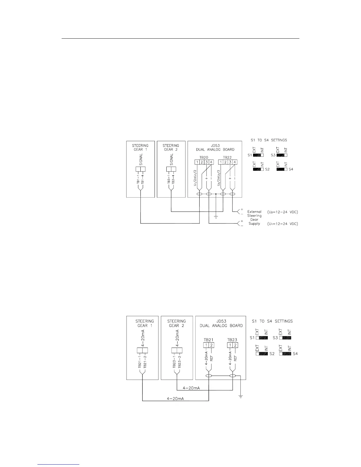
Voltage control with external reference
Figure 2-18 shows how an external reference voltage (12-24V)
is wired to the Dual Analog Board TB20 and TB22, terminals 3
and 4. With the external voltage return (terminal 4) as reference
the default rudder zero voltage and control range output at
terminals 1 and 4 will depend upon the external reference
voltage and can be adjusted in the Dockside setup (ref. page 55).
Note ! Jumpers S1 to S4 must be set to “EXT”, ref. Figure 2-22 to
identify the jumper locations.
Figure 2-18 Positive variable output, external reference
4 - 20 mA control
A 4-20 mA control signal is available at TB21 and TB23
terminals 1 and 2 as shown in
Figure 2-19. Rudder zero current
and control range can be adjusted in the Dockside setup (ref.
page ref. page
55).
Note ! Jumpers S1 to S4 must be set to “INT”, ref Figure 2-22 and
Figure 2-17.
Figure 2-19 4-20 mA Current Control