13
3. Overview, functional
description
3.1 General
Gear pump units are reservoir units with electrically driven gear
pumps that contain all hydraulic and electrical components
required for the operation of a piston metering device system or
an oil+air centralized lubrication system. Thanks to their
compact construction, gear pump units can be used to set up
piston metering device systems to lubricate small and mid-sized
machines, machine groups and systems very easily and with low
mounting effort.
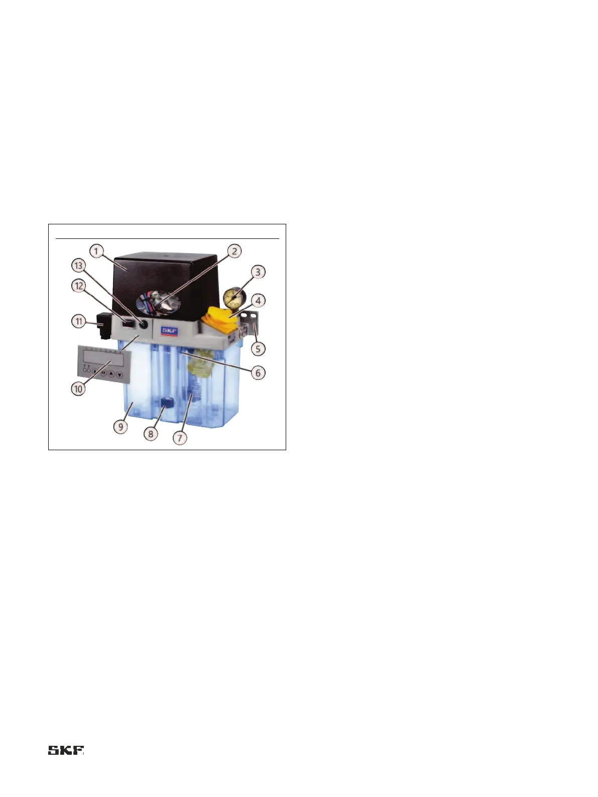
Equipment of an MKx gear pump unit (using MKU as an
example)
Legend to Figure 4:
1 Electric motor cover cap
2 Pressure switch
3 Pressure gauge
4 Filler neck with strainer (for oil) / filler neck without strainer
(for grease)
5 Pump unit holder
6 Pressure limiting valve / pressure relief valve
7 Gear pump unit
8 Lubricant level switch (float switch)
9 Lubricant reservoir(2-/3-/or 6-liter)
10 Gear pump unit without control unit (optionally with control
unit with 3- or 6-liter lubricant reservoir)
11 Plug supply voltage
12 Pushbutton (DK)
13 Control light (only on 3- or 6-liter reservoir)
3.2 Structure of a gear pump unit
In the basic design, gear pump units contain an electrically
driven gear pump (Fig. 5/7), a lubricant reservoir (Fig. 6/9)
(plastic = 2-, 3- and 6-liter rated capacity, metal= 3-liter rated
capacity), a pressure switch (Fig. 7/2) for electrical pressure
monitoring, a fill level switch (Fig. 8/8) monitoring the minimum
fill level, and a pressure gauge (Fig. 9/3) for visual pressure
monitoring. A pressure relief valve and a pressure limiting valve
are also mounted inside the gear pump unit. The filler neck
(Fig. 10/4) is accessible from outside the unit and is equipped
with a filling strainer (only on gear pump units for oil
lubrication).
The plastic reservoirs consist of transparent plastic that
allows visual inspection of the fill level. The metal reservoirs
(only on the oil design) contain a fill level indicator that likewise
allows visual inspection of the fill level. Due to the components
built into the reservoir, only a maximum of 80 % of the
theoretical reservoir capacity (rated capacity) can be used.
The pressure relief valve mounted in the gear pump unit is
required in order to relieve the system pressure built up during
a lubricating cycle to a residual pressure of ≤ 0.5 bar once the
motor is turned off. This is required for the operation of the
piston metering devices.
The pressure limiting valve mounted in the gear pump unit is
required in order to limit the maximum permissible system
pressure in the centralized lubrication system to a maximum
value. In the basic design, the pressure limiting valve in a gear
pump unit is set to a maximum system pressure of 30 bar. Gear
pump units are available in model designs with or without a
control unit. In the model design without a control unit, the gear
pump unit (and thus the lubrication interval) is controlled by the
control unit of the machine that the gear pump unit is mounted
on. In the model design with a control unit, the gear pump unit
is equipped with an electronic control unit that controls the gear
pump unit (and thus the lubrication interval).
In the model designs with or without a control unit, the
electrical connection to the supply voltage is established using a
rectangular connector (Fig. 11/11) as per DIN EN 175301-
803-A (clamping range Ø 8 to 10 mm). In the model design
without a control unit, the electrical connection to monitoring
units such as pressure switches and float switches is established
via a terminal strip. The electrical line is run outwards via a
screwed gland (clamping range Ø 6 to 12 mm or Ø 5 to 10 mm)
mounted on the gear pump unit.
In the model design with a control unit, the electrical
connection to the monitoring units such as pressure switches
and float switches is established inside the gear pump unit
directly to the connectors on the electronic control unit.
Depending on the control unit's model design, a signal line for
fault monitoring can be run outwards to connect to the machine
control unit via a cable fitting (clamping range Ø 6 to 12 mm or
Ø 5 to 10 mm) mounted on the gear pump unit.
Depending on the model design, the gear pump unit can be
equipped with an indicator lamp (Fig. 12/13) in a front panel. If
the indicator lamp is lit green, this indicates that the unit is
operating (pump motor running = lubricating). If the indicator
lamp is lit red, this indicates a malfunction (only on design with
a control unit). Depending on the model design, the gear pump
unit can be equipped with a pushbutton (Fig. 13/12) in a front
panel. The pushbutton is used for manually performing an
interim lubrication. The electrical circuit diagram of the gear
pump unit is affixed inside the unit's cover cap and can be

 Loading...


