EasyManuals Logo

SKF MKU Series Assembly Instructions

SKF MKU Series
68 pages
To Next Page IconTo Next Page
To Previous Page IconTo Previous Page
Page #46 background imageLoading...
Page #46 background image
46
Connections via:
1x connector XS1 (DIN EN 175301-803 A)
1x screwed gland
Fig. 78
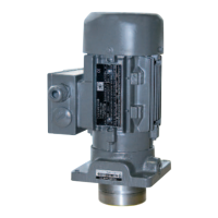
MKF1-12 B _ _ 1000+924, MKF2-12(4)B _ _ 1000+924,
MKF2-12(4)B _ _ 4000+924
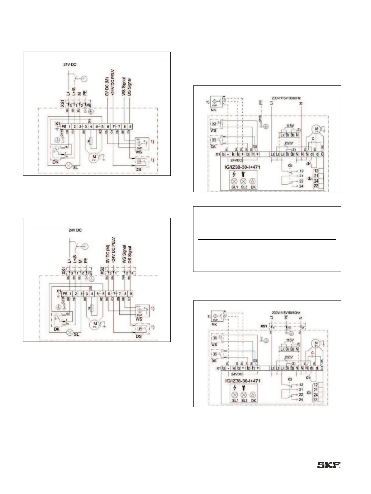
Connections via:
XS1 connector (DIN EN 175301-803 A)
XS2 connector (M12x1)
Fig. 79
MKF1-12 B _ _ 2000+924, MKF2-12(4)B _ _ 2000+924
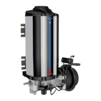
6.8.3 Terminal diagrams for MKU/MKF/MKL,
3- or 6-liter reservoir, with control unit
6.8.3.1 MKU, IG/IZ38 control unit, voltage design
230/115 VAC
Connections via:
2x screwed glands
Fig. 80
MKU2/5-12/3/4C/D _ _ 0000+428/+429
Table 10
Settings
Assignment
Operation
<Content>
d2:12
Fault
d2:24
Normal operation
d2:22
Fault
Connections via:
1x XS1 connector (DIN EN 175301-803 A)
1x screwed gland
Fig. 81
MKU2/5-12/3/4C/D _ _ 1000+428/+429

Table of Contents

Other manuals for SKF MKU Series

Questions and Answers:

Question and Answer IconNeed help?

Do you have a question about the SKF MKU Series and is the answer not in the manual?

SKF MKU Series Specifications

General IconGeneral
BrandSKF
ModelMKU Series
CategoryWater Pump
LanguageEnglish

Related product manuals