51
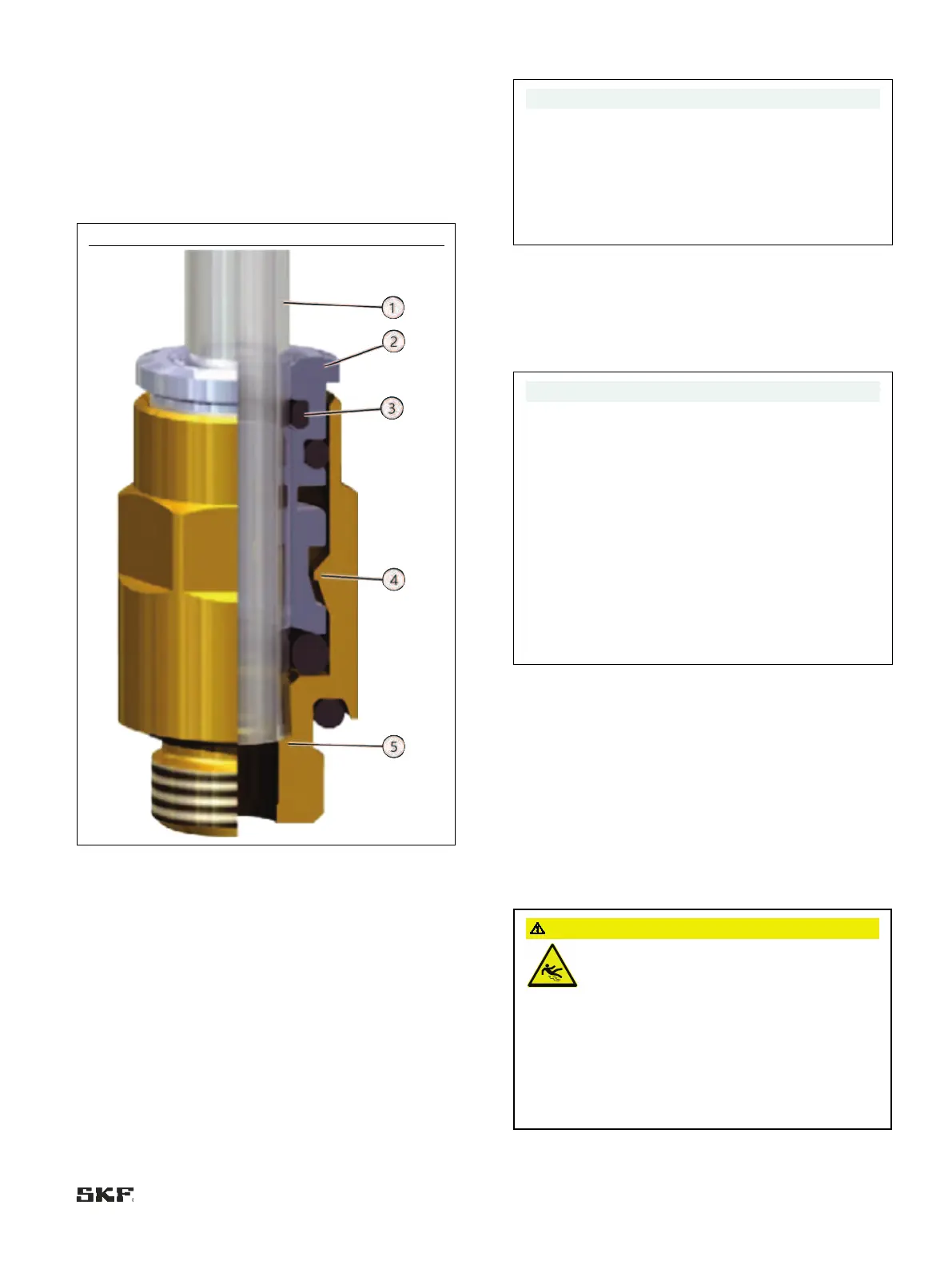
Legend to Figure 91:
1 Metal pipe
2 Collet
3 First O-ring
4 Locking claw
5 Claw groove
6 Mechanical stop
Quick coupling for plastic tube
Legend to Figure 92:
1 Plastic tube
2 Collet
3 First O-ring
4 Locking claw
5 Mechanical stop
1. Cut the connecting tube (Fig. 91 or 92/1) to the correct length
with a tube cutter (see Accessories)
During the following installation of the tube, a noticeable
resistance must be overcome when passing through the
first O
-ring (Fig. 91 or 92/3) and the locking claw
91 or 92/4) of the collet (Fig. 91 or 92/2). If a claw
groove is not used, fix t
he tube using appropriate fastening
hardware (e.g., mounting clips) to prevent the tube from
slipping out of the SKF quick coupling.
2. Insert the tube (Fig. 91 or 92/1) fully into the collet
(Fig. 91 or 92/2) of the SKF quick coupling until it passes the
first O-ring (Fig. 91 or 92/3) and the locking claw
(Fig. 91 or 92/4) of the collet (Fig. 91 or 92/2) and reaches
the mechanical stop (Fig. 91/5) or (Fig. 92/6)
To remove the metal tube (Fig. 91 /1) , press the collet
(Fig.
91/2) inward into the SKF quick coupling. The metal
91/1) can now be pulled out of the collet
91/2) of the SKF quick coupling.
To remove the plastic tube
(Fig. 92 /1), press the collet
92/2) inward into the SKF quick coupling. To do this,
also press the plastic tubing (Fig.
92/1) inward into the SKF
quick coupling fitting, which releases the collet (Fig.
92/2)
from the plastic tubing (Fig.
92/1). The plastic tube
92/1) can now be pulled out of the collet (Fig. 92/2) of
Before reassembling, shorten the end of the plastic
mm to ensure that the locking claw
(Fig. 92/4) of the collet (Fig. 92/2) functions properly.
6.12 System criteria for MKL gear pump
unit
The MKL gear pump unit can be used for oil+air centralized
lubrication systems. In this case, consult the corresponding
assembly instructions for the oil+air lubrication system when
assembling and designing the system.
6.13 General information on lubrication
line routing
Risk of slipping
Personal injury or property damage due to
contaminated areas
Centralized lubrication systems must always be
free of leaks.
Leaking lubricant is hazardous due
to the risk of slipping and injury.
Beware of any lubricant leaking out during
assembly, operation, maintenance, or repair of
centralized lubrication systems.
Leaks must be
sealed off without delay.

 Loading...


