49
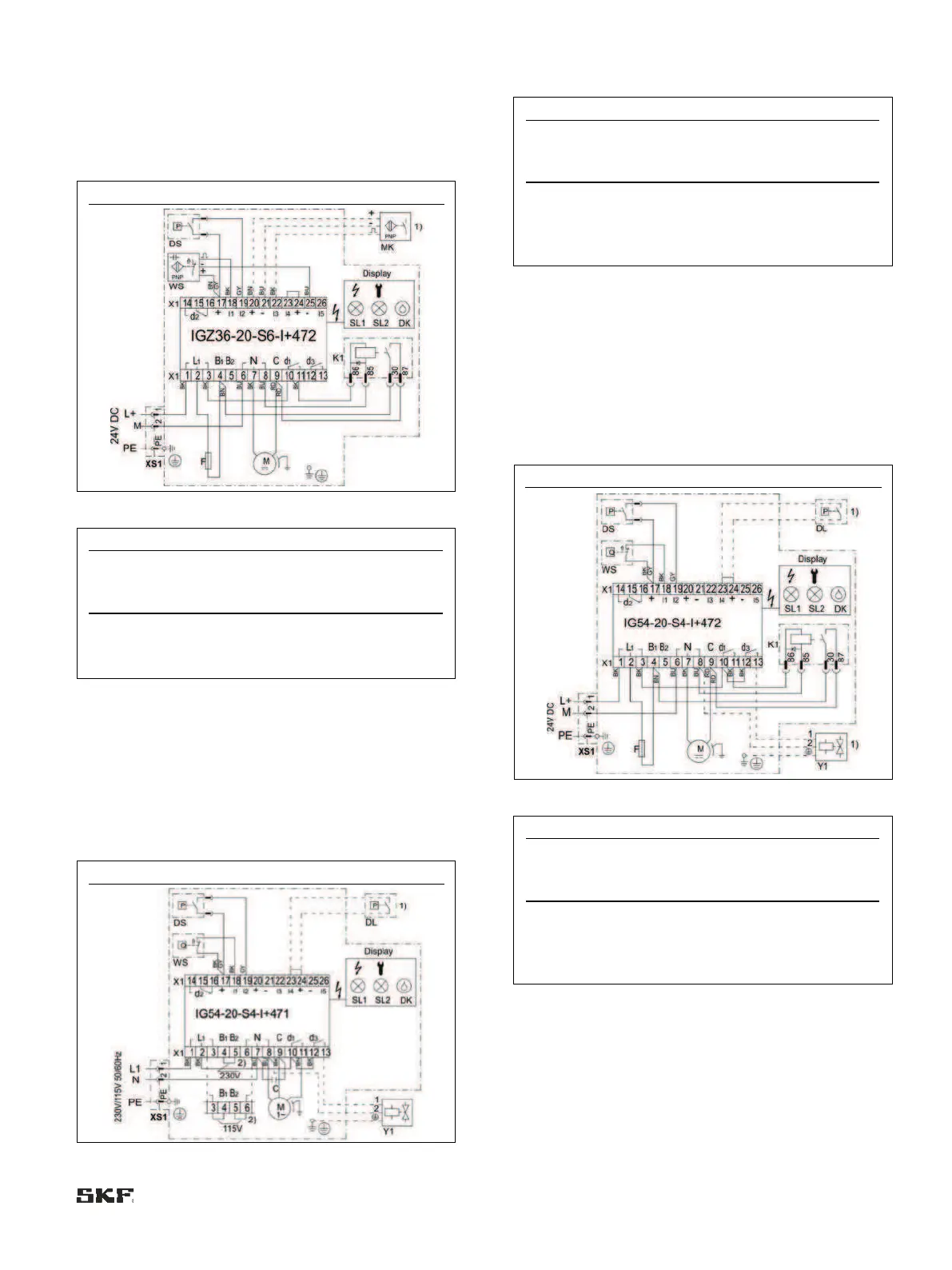
6.8.4.2 MKF, IGZ36 control unit, voltage design
24 VDC
Connections via:
• 1x connector XS1 (DIN EN 175301-803 A)
• 1x screwed gland
MKF2/5-12/4E _ _ 1000+924
1) Machine contact MK is only required in counter mode
(operating mode D)
6.8.4.3 MKL, IG54 control unit, voltage design
230/115 V AC
Connections via:
1x XS1 connector (DIN EN 175301-803 A)
1x screwed gland
MKL2/5-12/3/4F _ _ 1000+428/+429
Fault or completion of
prelubrication cycles
1) Customer-connectable air pressure switch DL, compressed-
air valve Y1
2) The control unit can be switched between 230 V and
115 V AC. The pump motor is not switchable!
6.8.4.4 MKL, IG54 control unit, voltage design 24 VDC
Connections via:
• 1x connector XS1 (DIN EN 175301-803 A)
• 1x screwed gland
MKL2/5-12/3/4F _ _ 1000+924
Fault or completion of
prelubrication cycles
1) Customer-connectable air pressure switch DL, compressed-
air valve Y1
6.9 Lubrication line connection
The main lubrication line must be mounted on the gear pump
unit in such a way that no forces are transferred to the unit
once assembled (stress-free connection).

 Loading...