33
In the case of electric switches with inductive loads, the
inductivity of the switch must be low in order to keep wear on
contact surfaces to a minimum. Otherwise, there is a risk of
damaging the contact surfaces on the switch elements.
Appropriate measures must be taken to protect the contacts of
the switch elements.
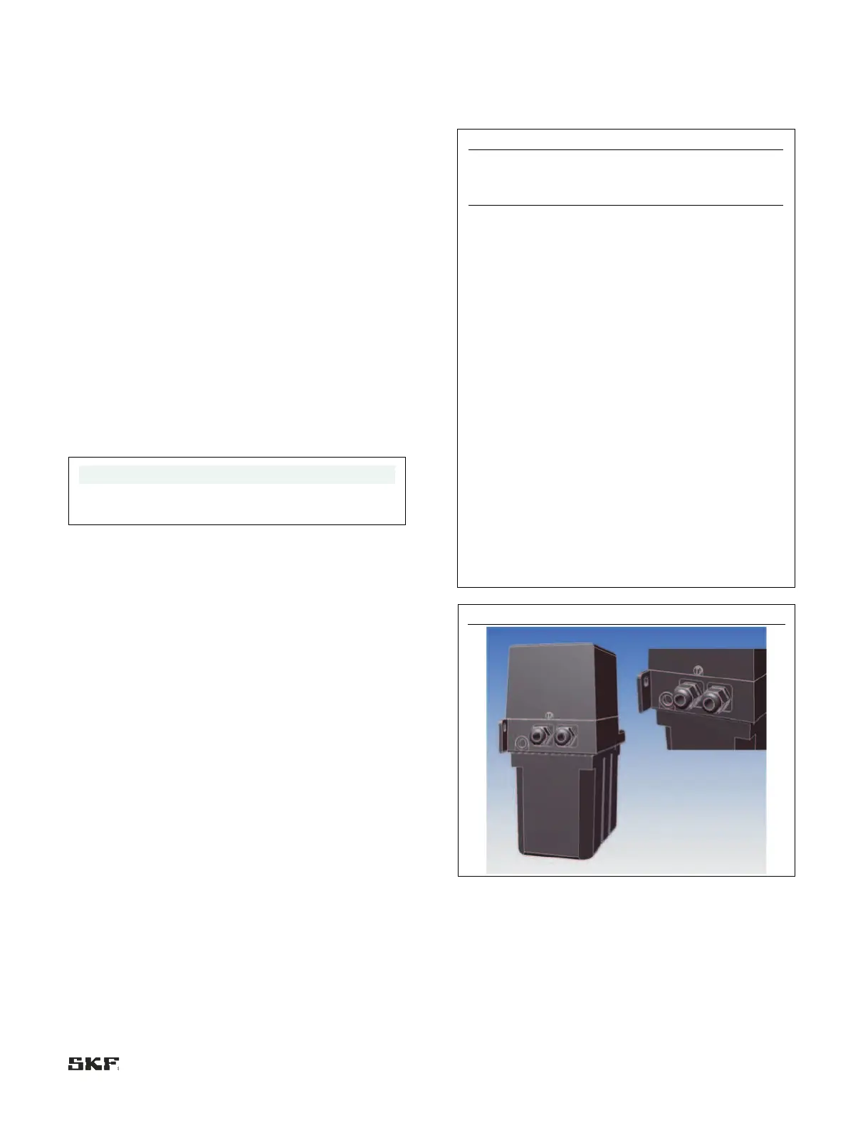
6.7.2 Electric motor connection with cable
socket and circular connector
• Connect customer-provided connector plugs for cable socket
(XS1) and circular connector (XS2) in accordance with the
wiring diagram on the inside of the cover cap or the figure
corresponding to the type number of the pump (Chapter 6.4
Assembly drawing with minimum mounting dimensions)
• Mount and tighten connector plugs
• Route the customer-provided connection cable in such a way
that it is free of stress and tension
6.7.3 Electric motor connection with screwed
glands
The cover cap (Fig. 1/2) is fastened with two slotted screws
(Fig. 1/3)
1. Using a screwdriver, only loosen the slotted screws (Fig. 1/3)
on both sides of the cover cap (Fig. 1/2); do not take them out
completely!
2. Carefully lift the cover cap (Fig. 1/2) and put it aside
3. Loosen the screwed gland (Fig. 1/4)
4. Draw the connection cable provided by customer into the
screwed gland (Fig. 1/4)
5. Connect the customer-provided connection cable in
accordance with the wiring diagram on the inside of the cover
cap or the figure corresponding to the type number of the
pump (6.4 Assembly drawing with minimum mounting
dimensions)
6. Tighten the screwed gland (Fig. 1/4)
7. Carefully put on the cover cap (Fig. 1/2), and tighten the
slotted screws (Fig. 1/4) evenly until finger-tight
8. Route the customer-provided connection cable in such a way
that it is free of stress and tension
6.8 Terminal diagrams
6.8.1 Legend to the terminal diagrams
Connection for operating voltage
Protective earth conductor
Pushbutton for intermediate lubrication
Control light (green) "Operation"
Control light (green) "Operation"
Control light (red) "Fault"
Plug connection per DIN EN 175301-
803 A
Optional: Contact closes at minimum level
(NO)
2x screwed glands
 Loading...


