EasyManuals Logo

SKF MKU Series Assembly Instructions

SKF MKU Series
68 pages
To Next Page IconTo Next Page
To Previous Page IconTo Previous Page
Page #23 background imageLoading...
Page #23 background image
23
2)
If control E is selected, only electrical connection 1 can be selected.
3)
Possible only with delivery rates 0.1 and 0.2 l/min.
4)
Only on design without control unit.
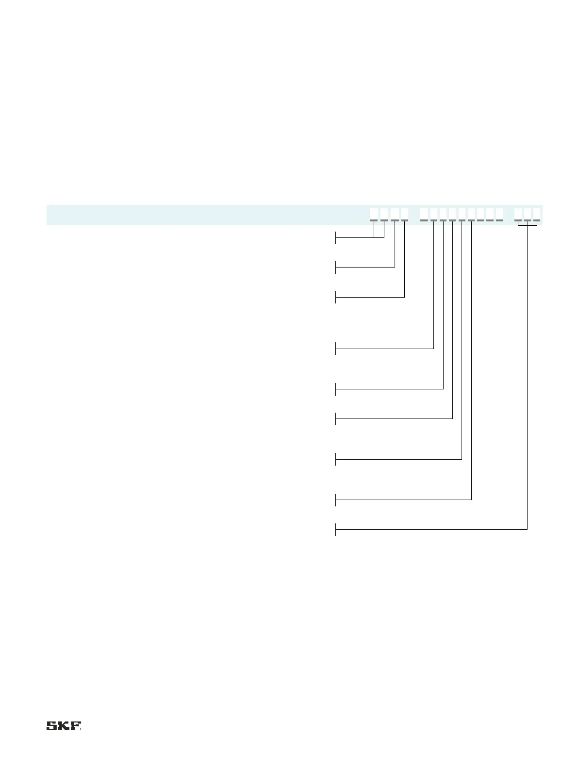
Order example:
MKF1-11AC10000+924
• Gear pump unit for fluid grease
• without control unit, with terminal strip
• Delivery rate 0.1 l/min
• Lubricant level switch NC contact, pressure switch NO contact
with pressure gauge
• 1st generation
• 2 screwed glands
• 2 liter plastic reservoir
• Voltage 24 V DC
4.4 Order code for MKL gear pump units
M
K
L
-
1
F
C
1
0
0
0
+
Product series
MK
MKx pump
Lubricant
L
for oil+air system
Delivery rate
1
0.1 l/min
"
"
-
2
0.2 l/min
"
"
"
5
0.5 l/min
"
"
"
Lubricant reservoir, control unit
Lubricant reservoir
2
3
4
3 liter plastic
3 liter metal
6-liter plastic
Control
F
Control unit IG54-20-S4
Monitoring
C
Monitoring unit with lubricant level switch (NC contact) and pressure
switch 20 bar (NO contact)
Pressure gauge
0
without pressure gauge
1
with pressure gauge
Electrical connection
1
1 screwed gland, 1 rectangular connector
Voltage code
Voltage
Frequency
Control
924
1)
24 V DC
-
A, B, E
428
230 V AC
50/60 Hz A, B, C, D, E
429
115 V AC
1)
Possible only with delivery rates 0.1 and 0.2 l/min.

Table of Contents

Other manuals for SKF MKU Series

Questions and Answers:

Question and Answer IconNeed help?

Do you have a question about the SKF MKU Series and is the answer not in the manual?

SKF MKU Series Specifications

General IconGeneral
BrandSKF
ModelMKU Series
CategoryWater Pump
LanguageEnglish

Related product manuals