18
3.7.3 Single-line lubrication systems with
piston metering devices
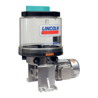
Single-line systems with piston metering devices generally
consist of a reservoir unit, and here include a gear pump unit,
piston metering devices, and lubrication lines. The pressure
limiting valve and pressure relief valve required for the
centralized lubrication system's operation are mounted in the
gear pump unit. If pressure losses of greater than 10 bar are
expected in the centralized lubrication system, for example due
to expansion of the system or due to the viscosity of the
lubricant (depending on the ambient temperature), a pressure
switch should be positioned before the last lubricant metering
device to monitor the centralized lubrication system. The
pressure switch monitors whether the required pressure build-
up occurs in the centralized lubrication system during the pump
cycle time. The pump delay time specified by the control unit or
machine control unit (8 to 15 seconds are recommended; other
delay times are possible depending on the layout of the
centralized lubrication system) ensures pressure build-up in the
centralized lubrication system. Pressure in the main lubricant
line must be relieved after the pump is switched off in order to
ensure proper functioning of the piston distributors. This is
performed by the pressure relief valve mounted in the gear
pump unit. On centralized lubrication systems with extended
main lubricant lines longer than 100 m, the main lubricant line
must be designed as a ring line (use the second pressure port P)
and the relief procedure in the centralized lubrication system
must be facilitated using additional valves (using the return
connection R).
3.7.4 Lubrication cycle sequence
The sequence of a lubrication cycle depends on the type of
piston metering devices in use. Piston metering devices are
differentiated into prelubrication metering devices and
relubrication metering devices. Piston metering devices
designed as prelubrication metering devices deliver the metered
quantity of lubricant at the same time that pressure is built up
in the lubricant line. Piston metering devices designed as
relubrication metering devices supply the metered quantity of
lubricant after the pressure relief procedure in the lubricant
line.
After the electric motor is switched on, the lubricant is drawn
out of the lubricant reservoir by the gear pump and fed through
the lubricant line to the prelubrication metering devices via the
pressure relief valve and the pressure limiting valve. The
pressure built up in the centralized lubrication system meters
the lubricant separately for each lubrication point and feeds it to
the consuming points. After the electric motor is switched off,
the pressure is relieved in the centralized lubrication system. In
this process, the lubricant is moved within the prelubrication
metering device from the spring chamber into the metering
chamber. The centralized lubrication system is ready for the
next lubrication cycle.
3.7.5 Lubrication cycle of relubrication
metering device
After the electric motor is switched on, the lubricant is drawn
out of the lubricant reservoir by the gear pump and fed through
the lubricant line to the relubrication distributors via the
pressure relief valve and the pressure limiting valve. The
pressure built up in the centralized lubrication system feeds the
lubricant into the storage chamber of the relubrication metering
devices. After the electric motor is switched off, the pressure is
relieved in the centralized lubrication system. In this process,
the lubricant is metered within the relubrication distributor and
delivered to the lubrication point (relubrication effect). After the
lubricant has been completely expelled to the lubrication point,
the centralized lubrication system is ready for the next
lubrication cycle.
 Loading...
