32
Overvoltage
Damage and injury due to improper connection of the
supply voltage
• The available line voltage (supply voltage) must match
the specifications on the rating plate of the motor or the
rating plate of the electrical components.
Check the fuse protection of the electrical circuit.
• Use only fuses with appropriate amperage.
Electrical connection
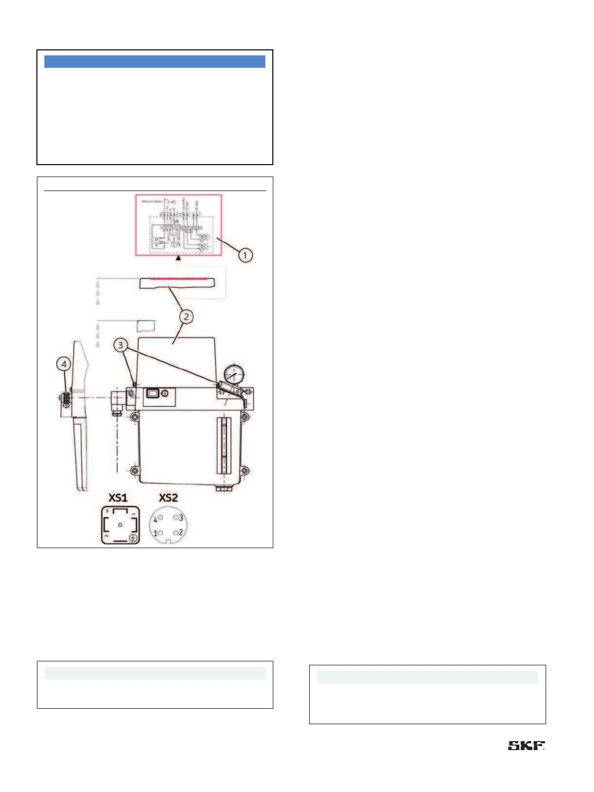
Legend to Figure 27:
1 Cover cap
2 Connection diagram
3 Slotted screws
4 Screwed gland
XS1 cable socket according to DIN EN 175301-803-A
XS2 circular connector, 4-pin, M12x1
Lightly loosen the slotted screws (Fig. 1/3) of the cover cap
(Fig. 1/2) only; do not take them out completely
6.7.1 Electric motor connection
Consult the motor's type plate for the electrical characteristics of
the motor.
Observe the guidelines in EN 60034-1 (VDE 0530-1) for
operation at the limits of the ranges A (combination of
±5 % voltage deviation and ±2 % frequency deviation) and B
(combination of ±10 % voltage deviation and +3/-5 % frequency
deviation). This applies especially with regard to deviations in
operating parameters from the ratings on the motor's type
plate. The limits must never be exceeded.
Be sure to connect the motor so as to guarantee a
continuously safe electrical connection (no protruding wire
ends); use the assigned cable end fittings (e.g. cable lugs, wire
end ferrules). Select connecting cables conforming to
DIN VDE 0100, taking into account the rated current and the
conditions of the specific system (e.g. ambient temperature,
type of routing etc. in accordance with DIN VDE 0298 and
EC / EN 60204-1). Details regarding electrical connection of the
motor to the power supply, especially terminal and connector
pin assignment, can be taken from the following motor data
table or customer's drawing (if available).
When establishing the gear pump unit’s electrical connection,
ensure that appropriate measures are taken to prevent
interference between signals due to inductive, capacitive, or
electro-magnetic couplings. Shielded cables must be used if
electrical interference fields affect signal transmissions despite
separate laying of cables. Ensure that cables are arranged in an
EMC-compliant manner. Gear pump units are powered by
electric motors. Depending on the model design, AC motors or
DC motors are used. The basic design of AC motors is a
capacitor motor for 230 V 50/60 Hz and 115 V 50/60 Hz
single-phase alternating current; the basic design for DC motors
is for 24 V direct current. On a gear pump unit with or without a
control unit, the electrical connection is established by the
following depending on the control/monitoring:
• 2 screwed glands
• 1 screwed gland and a rectangular connector (XS1) acc. to
DIN EN 175301-803-A
• 1 circular connector M12x1 (XS2) and a rectangular
connector acc. to DIN EN 175301-803-A
• 1 plug and a screwed gland
• 1 plug and a rectangular connector acc. to DIN EN 175301-
803-A
In the design with a control unit, the motor is connected to
the electronic control unit.
The connection wiring is in accordance with the electrical
circuit diagrams in sections 6.8.2 Terminal diagrams for
MKU/MKF, without control unit, 6.8.3 Terminal diagrams for
MKU/MKF/MKL, 3- or 6-liter reservoir, with control unit and
6.8.4 MKF, IG/IZ38 control unit, voltage design 230/115 VAC.
The electrical circuit diagram of the gear pump unit is also
displayed inside the cover cap (Fig. 27/2) of the unit and can be
accessed by removing the cover cap.
For a gear pump unit with control unit, also consult the
operating instructions for the control unit.
They come
 Loading...


