EasyManuals Logo

SKF MKU Series Assembly Instructions

SKF MKU Series
68 pages
To Next Page IconTo Next Page
To Previous Page IconTo Previous Page
Page #34 background imageLoading...
Page #34 background image
34
Fig. 29
XS1 connector, XS2 connector
Fig. 30
XS1 connector, screwed gland
Fig. 31
Terminal strip, item 1 to 9
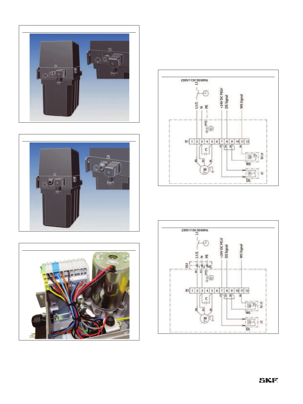
6.8.2 Terminal diagrams for MKU/MKF,
without control unit
6.8.2.1 MKU, 2-liter reservoir, voltage design
230/115 VAC, without pushbutton
Connections via:
2x screwed glands
Fig. 32
MKU1-11A _ _ 0000+428/+429, MKU1-11A _ _
3000+428/+429
Connections via:
1x connector XS1 (DIN EN 175301-803 A)
1x screwed gland
Fig. 33
MKU1-11A _ _ 1000+428/+429, MKU1-11A _ _
4000+428/+429

Table of Contents

Other manuals for SKF MKU Series

Questions and Answers:

Question and Answer IconNeed help?

Do you have a question about the SKF MKU Series and is the answer not in the manual?

SKF MKU Series Specifications

General IconGeneral
BrandSKF
ModelMKU Series
CategoryWater Pump
LanguageEnglish

Related product manuals