47
1) Machine contact MK is only required in counter mode (IZ38-
30-I control unit)
2) The control unit can be switched between 230 V and
115 V AC. The pump motor is not switchable!
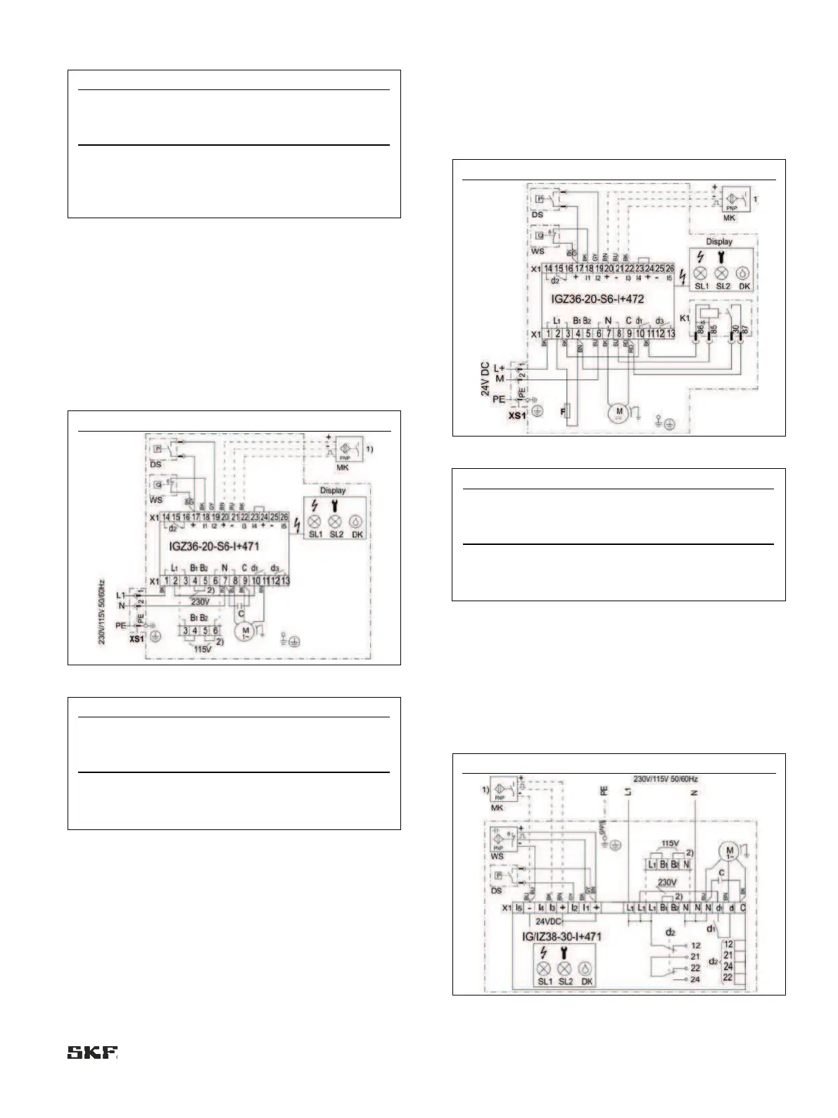
6.8.3.2 MKU, IGZ36 control unit, voltage design
230/115 VAC
Connections via:
• 1x connector XS1 (DIN EN 175301-803 A)
• 1x screwed gland
MKU2/5-12/3/4E _ _ 1000+428/+429
1) Machine contact MK is only required in counter mode
(operating mode D)
2) The control unit can be switched between 230 V and
115 V AC. The pump motor is not switchable!
6.8.3.3 MKU, IGZ36 control unit, voltage design
24 VDC
• Connections via:
• 1x connector XS1 (DIN EN 175301-803 A)
• 1x screwed gland
MKU2/5-12/3/4E _ _ 1000+924
1) Machine contact MK is only required in counter mode
(operating mode D)
6.8.4 MKF, IG/IZ38 control unit, voltage
design 230/115 VAC
Connections via:
• 2x screwed glands
MKF2/5-12/4C/D _ _ 0000+428/+429
 Loading...


