19
6 SKF SAFEFLOW FLOWMETERS SF05A, SF10A, SF15A, SF20A, SF30A
6.1 SKF Safeflow flowmeter’s technical description
SKF Safeflow oil flowmeters function on the rotameter principle. This method can be set very accurately,
whatever the temperature, viscosity or operating pressure.
6.1.1 Main components
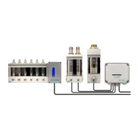
The SKF Safeflow oil flowmeter unit is a modular product consisting of one or several measuring units with a
beam structure.
The term meter refers to a measuring structure that can be set separately and the meter unit consists of one
or several meters.
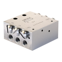
The input and output connections for a meter unit are located in a strongly built aluminium casing. The flow
monitoring tubes are made of heat-resistant glass. A float is used for measuring and the flow is controlled by
constriction. Each meter can be set separately according to the required flow.
The SF05A, SF10A and SF15A meters also make it possible to use three flow ranges, since they can be con-
verted with the SF05A-KIT4 modification kit, SF10A-KIT4 modification kit or SF15A-KIT4 modification kit.
The meter unit is fixed to the installation base by placing locking screws in the rectangular slot in the back of
the frame and by tightening the frame with locking nuts in a suitable place on the back board or fixing bar. The
sensors for electronic flow monitoring, supplied as options or installed later, are fitted to the meters.
6.1.2 Operating principle
The oil enters the meter unit from the lower connection at the back of the frame (in exceptional cases the oil
enters from the connection at the end of the frame).
An adjusting valve is located in the feed opening for each meter and the oil moves through its flow opening to
the meter section. A feature of the adjustment valve is that the surface area of the flow opening changes by
sector and not in rings as in older pin or cone valves.
Under normal operating conditions the described constriction valve will not block. The meter has a cylindrical
glass tube in which the adjustable cone and ring-shaped float are located.
With a ring-shaped float, the flow remains visible even when the oil is of a dark colour since it flows though the
float.
The oil flows from the measuring section at a set rate through the output connection along a tube to the lubri-
cation point. The output connection is at the back of the frame above the input connection. There is an output
connection for each meter.
6.2 Technical specifications
6.2.1 Specifications
Table 1. Flow rate range