49
7.5.1 Connecting the sensors
The sensors are connected to the terminal blocks 21 - 40 on the electronic card. Make sure to check that the
wires of the sensors are connected in the correct direction. The colour codes, brown and blue, are also
marked on the card.
From the jumpers J1 to J10, the jumpers corresponding to the unconnected sensor positions are removed.
7.5.2 External connections
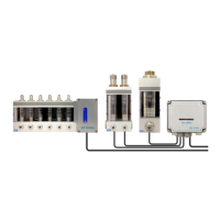
The connections are made as shown in Figure 23, External connections.
The supply voltage is connected to poles 1 and 3 of connector X1. The DC voltage polarity does not matter.
The supply voltage limit values are:
24V DC (20 - 36V DC) or
24V AC (17 - 27V AC RMS)
Max. power consumption: 150 A
The connection of the earth conductor is necessary in terms of the EMC characteristics of the system.
Alarm outputs are provided by terminal blocks 41 to 60. The relay contacts are openable in an alarm mode.
The maximum contact load is 50VAC/DC, 0.3A.